6 BASIC INSTRUCTIONS
6.8 Other Convenient Instructions
349
6
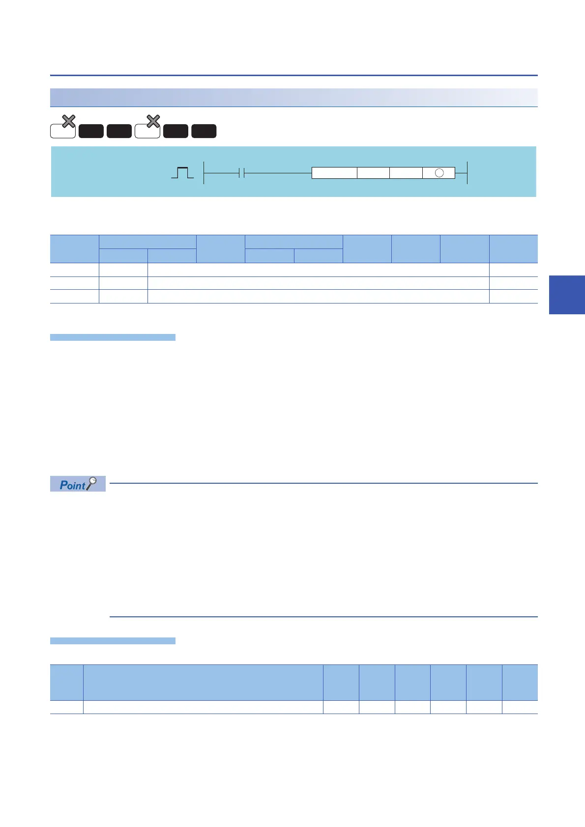
Fixed cycle pulse output
PLSY
*1 Only output (Y) can be used.
• Outputs a pulse at a frequency designated by n1 the number of times designated by n2, to the output module with the
output signal (Y) designated by (D).
• Frequencies between 1 to 100Hz can be designated by n1. If n1 is other than 1 to 100Hz, the PLSY instruction will not be
executed.
• The number of outputs that can be designated by n2 is between 0 to 65535 (0000H to FFFFH). If n2 is set to "0", pulses are
continuously output.
• Only an output number corresponding to the output module can be designated for pulse output at (D).
• Pulse output commences with the command rising edge of the PLSY instruction. Pulse output is suspended when the
PLSY instruction command goes OFF.
• With the PLSY instruction, the argument device data is registered in the work area of the CPU module and
counting operation is processed as a system interrupt. (The device data registered in the work area is
cleared by turning the execution command OFF, or turning the STOP/RUN switch STOPRUN.) For this
reason, the pulses that can be output must have longer ON and OFF times than the interrupt interval of the
CPU module. The interrupt interval of the CPU module is 1ms.
• Do not change the argument for the PLSY instruction during pulse output directed by the PLSY instruction
(while the execution command is ON). To change the argument, turn OFF the execution command.
• The PLSY instruction can be used only once in all programs executed by the CPU module. The second and
the subsequent PLSY instructions are not processed.
• In any of the following cases, an operation error occurs, the error flag (SM0) turns ON, and an error code is stored into SD0.
n1: Frequency or the number of the device where frequency is stored (BIN 16 bits)
n2: Outputs count or the number of the device where the outputs count is stored (BIN 16 bits)
(D): Number of the device to which pulses are output (bits)
Setting
data
Internal device R, ZR J\ U\G Zn Constant
K, H
Others
Bit Word Bit Word
n1
n2
(D)
*1
Error
code
Error details Q00J/
Q00/
Q01
QnH QnPH QnPRH QnU LCPU
4101 The device specified by (D) exceeds the range of the corresponding device.
Basic
Redundant
Process
High
performance
Universal
LCPU
 Loading...


