7 APPLICATION INSTRUCTIONS
7.5 Data Processing Instructions
433
7
Dissociation of random data, linking of random data
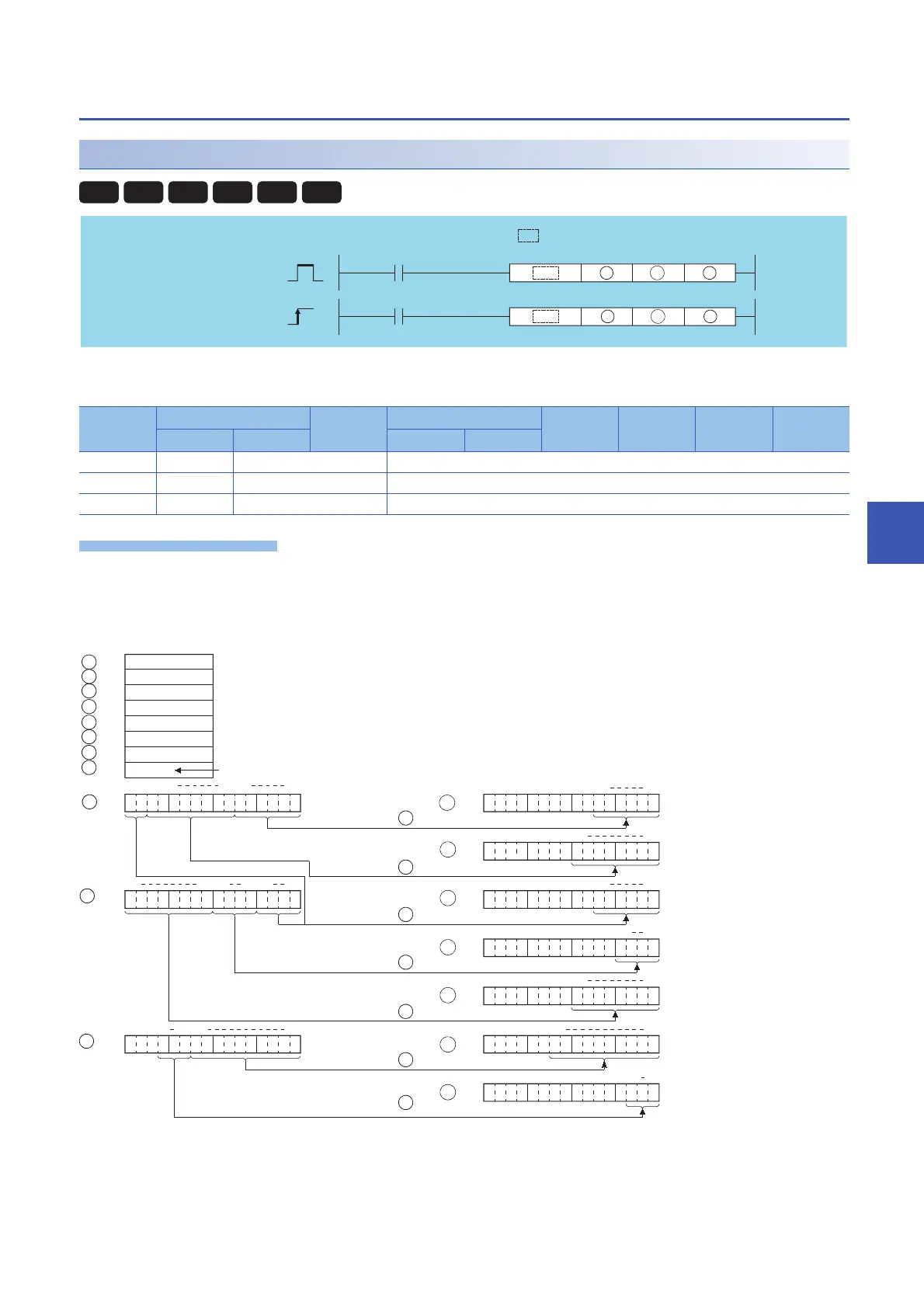
NDIS(P), NUNI(P)
■NDIS
• Dissociates data stored in device numbers starting from that designated at (S1) into the number of individual bits
designated at (S2), and stores this data in device numbers starting from that designated at (D).
(S1): Head number of the devices where data to be dissociated/linked is stored (BIN 16 bits)
(D): Head number of the devices where the dissociated/linked data will be stored (BIN 16 bits)
(S2): Head number of the devices where the units of dissociation/linking will be stored (BIN 16 bits)
Setting
data
Internal device R, ZR J\ U\G Zn Constant Others
Bit Word Bit Word
(S1)
(D)
(S2)
Basic
Process
High
performance
Redundant
Universal
LCPU
Command
Command
P
NDIS, NUNI
NDISP, NUNIP
S1
S2
S1
D
S2
D
indicates an instruction symbol of NDIS/NUNI.
Number of bits
designated at
6
4
8
3
0
Designation of the end of setting
Designation of the number of dissociated bits
b0
b5
b0
b7
b0
b5
b0
b3
b0
b7
b0
b9
b0
b2
b0
b5b6b15
b14
b13
b8
b15 b3 b0b4
b7
b12 b10 b0b9
8
6
10
S1
S2
D
S2
S2
S2
S2
S2
S2
S2
S1
S
1
S2
D
D
D
D
D
D
+1
+1
+2
+3
+4
+5
+6
+7
+1
+2
+6
+5
+4
+3
Number of bits
designated at +1
S2
Number of bits
designated at +2
S2
Number of bits
designated at +3
S2
Number of bits
designated at +4
S2
Number of bits
designated at +5
S2
Number of bits
designated at +6
S2
 Loading...


