Chapter Three: Installation and Configuration Mounting Hardware
26
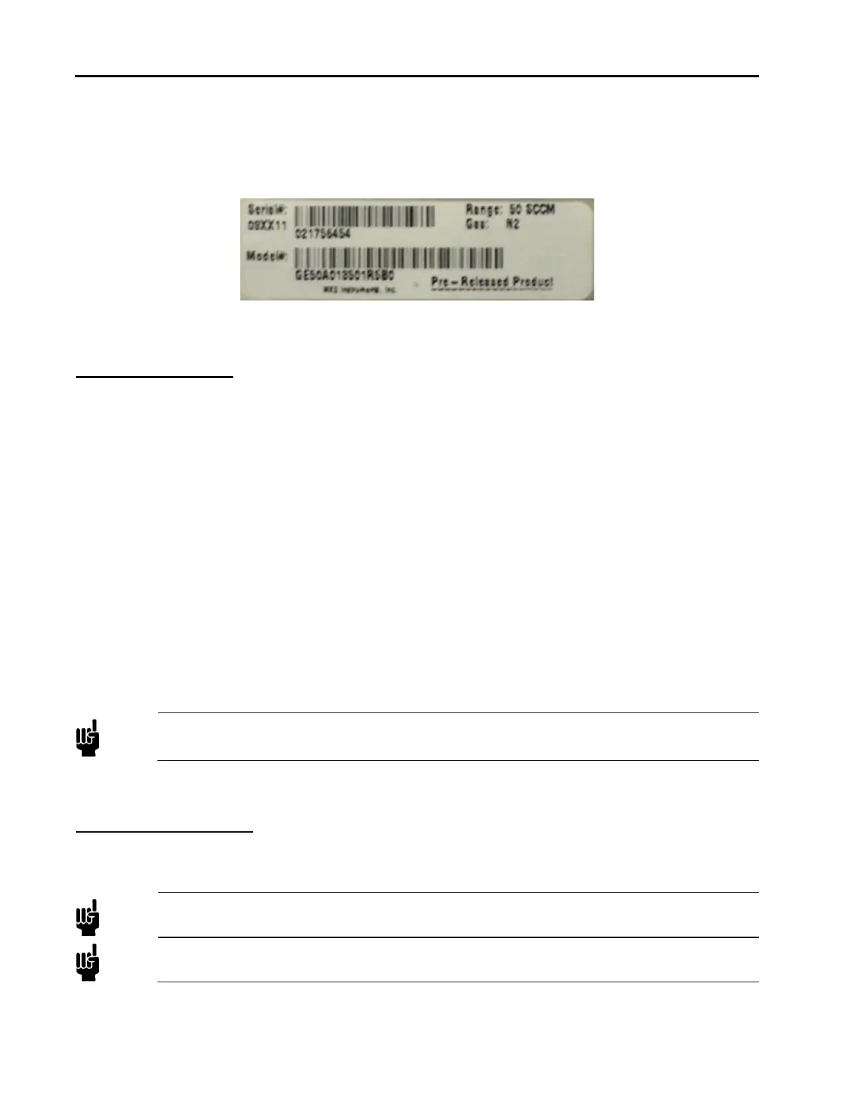
Serial Label
Each MFC has one serial number label. Each label shows the serial number, the model code, the full scale
flow range, and the calibration gas. The label is located on the MFC’s body below the pinout label on the
device’s enclosure.
Figure 1: Serial Number Label (sample)
Mounting Hardware
GE50A and GM50A MFCs with in-line fittings (VCR) have four threaded mounting holes located on the
bottom or base of the unit: two #8-32 and two M4. Depending on the hole pattern chosen, use #8-32 UNC-2B
or M4 hardware to mount the instrument. The outline drawings in Appendix C show the location and
dimensions of the mounting holes for standard axial fittings.
The GM50A MFC’s C-Seal and W-Seal downmount fittings are designed for device mounting using four
M5-0.8 x 30 mm long, socket head cap screws. In addition, C-Seal units may be mounted using 10-32 UNF x
1.25” long socket head cap screws if your mounting substrate requires.
GV50A MFCs are mounted on a baseplate which is attached to the base of the MFC body and the base of the
integral shut-off valve body. The four slots, one in each corner of the baseplate are to be used to mount and
secure the MFC. The outline drawings in Appendix D show the location and dimensions of the mounting
holes in the baseplate.
Control Valve – Not a Shut-off Valve
The control valve is not a positive shutoff valve. Some leakage across the valve may occur. Refer to
Appendix A, Product Specifications, page 79, for the leak integrity specifications. If necessary, install a
separate positive shutoff valve in your system.
Note
Connect the MFC to your system so that the gas flows in the direction of the flow arrow on the
front of the unit.
Installation Procedure
Install the MFC
Note
DO NOT make any electrical connections to the MFC until directed to do so.
Note
Information on electrical connections (pinouts and settings) is found in the following chapter.