Digital Interface Input and Output Options Chapter Four: Analog and Digital Interfaces
39
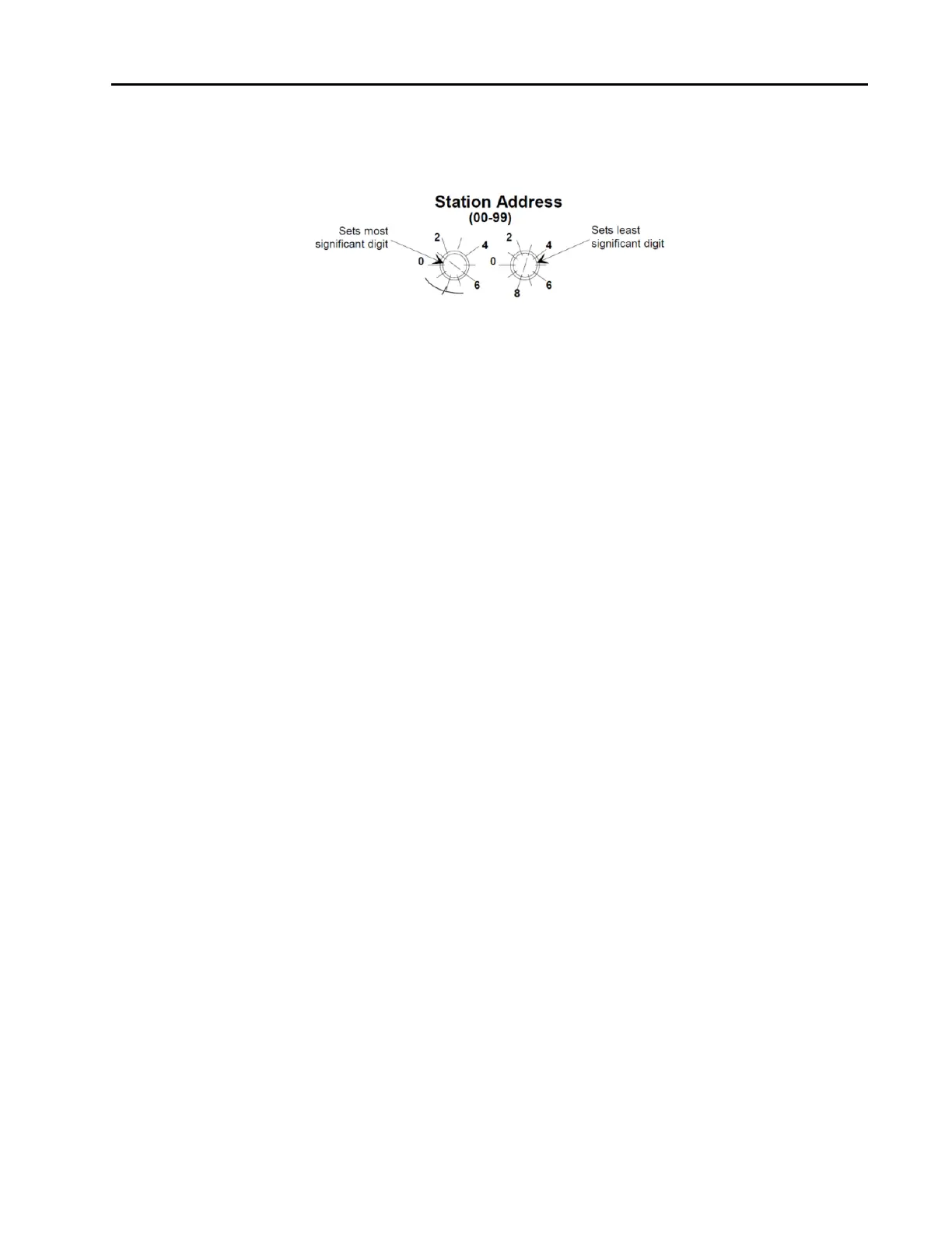
Station Address Switches
Two 10-position rotary switches, shown in Figure 15, are used to set the station address.
The station address is an integer identification value assigned to each node on the Profibus network.
Figure 7: Profibus Station Address Switches
The valid STATION ADDRESS switch positions are 0 to 99. Use the switch on the left to set the most
significant digit (MSD), that is, the factor of ten (10, 20, 30...90). Use the switch on the right to set the least
significant digit (LSD), that is, the increments of one (1, 2, 3...9). The switch positions are numbered in a
clockwise direction, to correspond to the increasing address values.
Power Up
This is the power-up sequence of the LEDs.
1. MOD LED is set to solid RED if SYSTEM_ERROR in the Small Receive Data is set, otherwise it is
set to solid GREEN.
2. NET LED is set to solid GREEN if the module is in idle state. It is set to about 2 Hz blinking GREEN
if the module is in executing state (check Device Status in Slot 30, Index 9).
3. NET LED is set to about 5 Hz blinking red if the WINK_STATUS is set to 1 and stops blinking
RED if WINK_STATUS is set to 0.
Warm-Up and Zero the MFC
After installation and power up, allow the MFC to warm up for a minimum of 30 minutes, then refer to the
installation section to Zero the MFC.
Warm Up Time
After installation and power connection, allow the MKS MFC to warm up for a minimum of 30 minutes.
This is to account for both warm-up of the device electronics as well as for the device to reach ambient
temperature conditions.
Zeroing the Device
Although MKS flow devices are zeroed at the factory prior to shipment, it is normal to check the zero and re-
zero them, if needed, when they are first installed on the tool.
A mass flow meter or mass flow device will provide a zero output signal under no flow gas conditions.
Zero offset from improper zeroing procedures can contribute to flow measurement inaccuracy. This is more
apparent at the lower end of the device flow range.
In order to complete a true zeroing of the device, ensure the following conditions are satisfied prior to
beginning the procedure.
Device is installed in the orientation intended for final use (i.e. horizontal base down, vertical flow up,
etc.).