Chapter Four: Analog and Digital Interfaces Analog Interface Input and Output Options
30
5. In selecting the appropriate type and wire size for cables, consider:
Voltage ratings.
Cumulative I
2
R heating of all the conductors (keep them safely cool).
IR drop of the conductors, so that adequate power or signal voltage gets to the device.
Capacitance and inductance of cables that handle fast signals (such as data lines or stepper motor
drive cables).
Some cables may need internal shielding from specific wires to others.
Analog Interface Input and Output Options
These analog I/O types are included for future reference. They were not available at the time this
manual was written.
The G-SERIES analog I/O MFC is available with either a 9 pin D male connector or a 15 pin D male
connector for providing power and signal I/O.
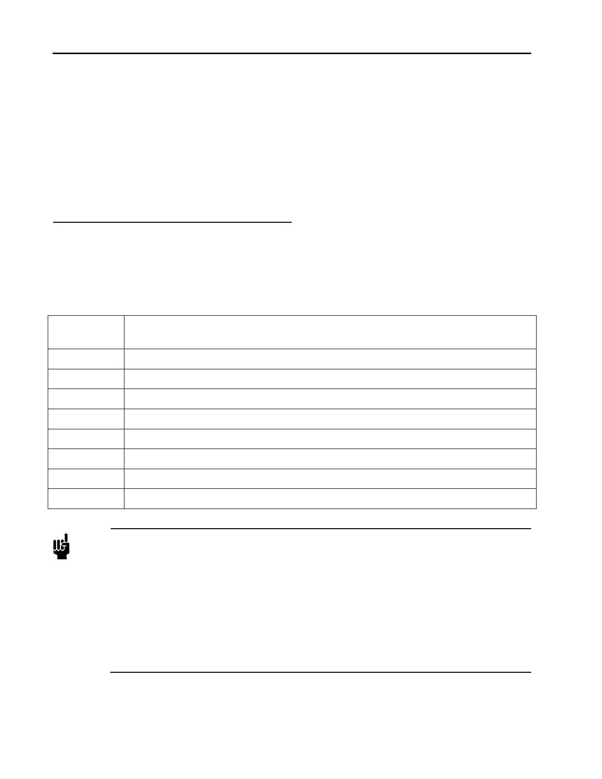
Table 8: Analog Interface Voltage I/O (0 to 5 VDC) – 9 Pin D Male Pinouts – Model Code A
Pin 1 Valve Open/Close: Apply +5 to+15 VDC to Open; Pull to ground or apply -5 to -15
VDC to Close.
Pin 2 Flow Output Signal, 0 to5 VDC (into high impedance load, minimum 10K-ohm)
Pin 3 +15 to +25 VDC :Power
Pin 4 Power Common
Pin 5 No Connection
Pin 6 Setpoint Input, 0-5 VDC
Pin 7 Signal Common
Pin 8 Signal Common
Pin 9 Valve Test Point
Notes
1. Chassis ground is not available on a separate pin. Instead, it is carried out through the cable
shielding. Be sure that the connector on the other end of the cable is properly grounded to its
chassis ground.
2. The 0 to 5 VDC flow signal output comes from pin 2 and is referenced to pin 7 (signal
common).
3. Use any appropriate 0 to 5 VDC input signal of less than 1K ohm source impedance
referenced to pin 7 as the setpoint signal to pin 6.
4. A signal common line MUST be connected to the power common line at either at the tool
end or at the MFC 15 pin D connector end of the cable to avoid setpoint/readback offsets.
DO NOT connect a signal common line and the power common line at both ends of the
cable as this will result in ground loops.