Digital Interface Input and Output Options Chapter Four: Analog and Digital Interfaces
33
Normal Setpoint operation occurs when Pin 1 is allowed to float.
If the MFC is equipped with a 15-pin Type D connector:
To Open the valve by applying a +5 to +15 VDC to pin 4.
To Close the valve by applying a -5 to -15 VDC low to pin 3 or connect pin 3 to the power ground
pin.
Priority of the Valve Commands
The MFC executes commands based on a hierarchical command structure. The highest priority command is
Valve Open, followed by Valve Close, and Setpoint Control. Therefore, if the flow controller is operating
under Setpoint Control, you can send a Valve Open command to force the valve to the full open position.
Note
When both the Valve Close and Valve Open pins are pulled down, the Valve Open command
takes precedence and the valve is moved to the open position.
Digital Interface Input and Output Options
The G-SERIES digital I/O MFC is available with either the DeviceNet, Profibus or RS485 communications
protocol. The specific protocol is specified at the time of order.
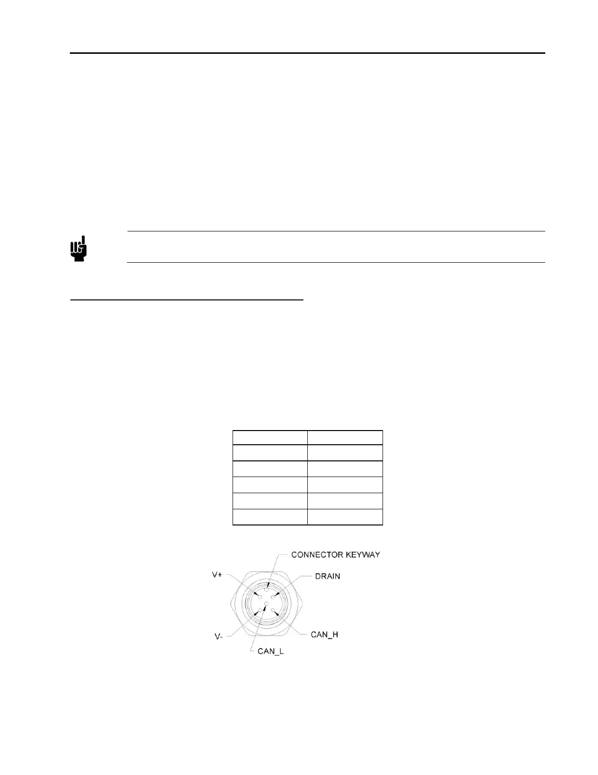
DeviceNet Digital Interface Using 5 Pin Microconnector
The MFC has one 5-pin, male DeviceNet connector that provides the communications interface with the
DeviceNet network, electrical power from the network bus, and shielding for the instrument signals.
Table 10: Digital Interface - DeviceNet Connector Pinout – Model Code 6
Pin Number Signal Name
1 Drain
2 V+
3 V-
4 CAN_H
5 CAN_L
Figure 2: DeviceNet Connector Pin Diagram
Overview of MFC DeviceNet Digital Operation