Chapter Four: Analog and Digital Interfaces Digital Interface Input and Output Options
38
Table 12B: Profibus 9 Pin D Female Communications Connector – Model Code 4
Communications Connector – 9 pin D female
Pin 1 No Connection
Pin 2 No Connection
Pin 3 B Line (RXD/TXD-P) Bus Positive
Pin 4 ISO_RTS (CNTR – P (Control for Repeater)
Pin 5 ISO_GND (Digital Ground)
Pin 6 ISO_VCC (Power Supply (5 V)
Pin 7 No Connection
Pin 8 A Line (RXD/TXP – N) Bus Negative
Pin 9 No Connection
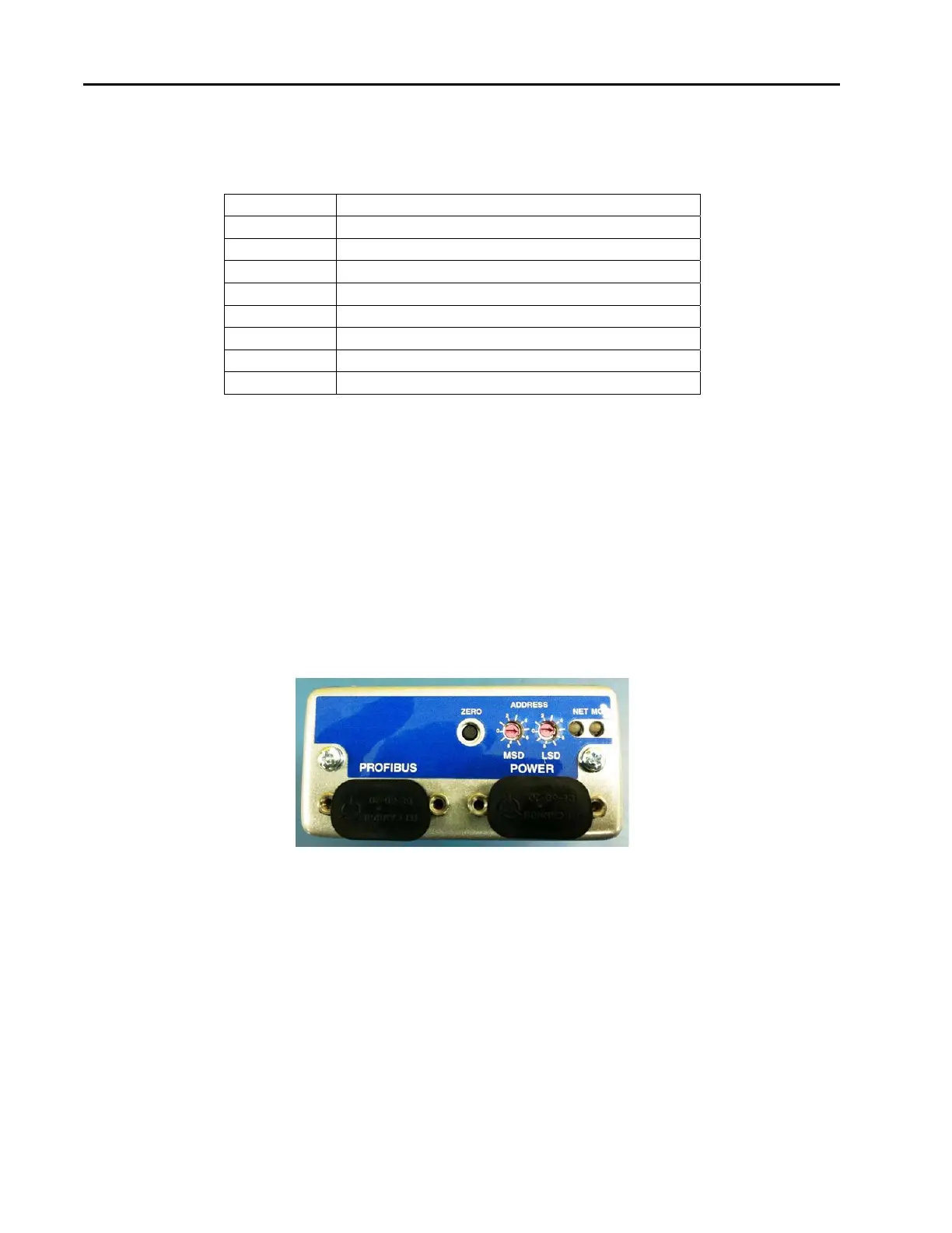
Profibus Controls and Indicators
The MKS G-Series Profibus mass flow device contains several Profibus controls and indicators located on the
top of the device enclosure. There are two switches which are used to set the Station Address and two
standard bi-color (green/red) Profibus status LEDs, (Module Status LED and Network Status LED). The
LEDS provide an indication of the device status. At power-up, the device performs checks on its
communications link and internal diagnostic checks of the EEPROM and RAM. The results of these checks
are indicated by the color (green or red) and illumination condition of the status LEDs on top of the
instrument. The Module and Network Status LED’s illuminate solid GREEN when initialization is complete.
The Network Status LED illuminates flashing GREEN when the device establishes communication with other
devices on the network.
Figure 6: Profibus Top View
Station Address
The address (station address) for the device is set using the rotary switches (MSD and LSD) located on the
top panel of the device. The address switches allow you to easily configure units without an operational
network, or to network multiple units quickly.
The address is read from the non-volatile memory. Any changes to the values must be made over the network;
any changes in the rotary switch positions after power-up are ignored.