Analog I/O Interface Cables Chapter Four: Analog and Digital Interfaces
29
Chapter Four: Analog and Digital Interfaces
Analog I/O Interface Cables
As of January 1, 1996, all products shipped to the European Community must comply with the EMC Directive
89/336/EEC, which covers radio frequency emissions and immunity tests. MKS products that meet these
requirements are identified by application of the CE Mark.
This MKS product meets CE Mark requirements, per EMC Directive 2004/336/EEC. To ensure compliance
when installed, an overall metal braided shielded cable, properly grounded at both ends, is required during
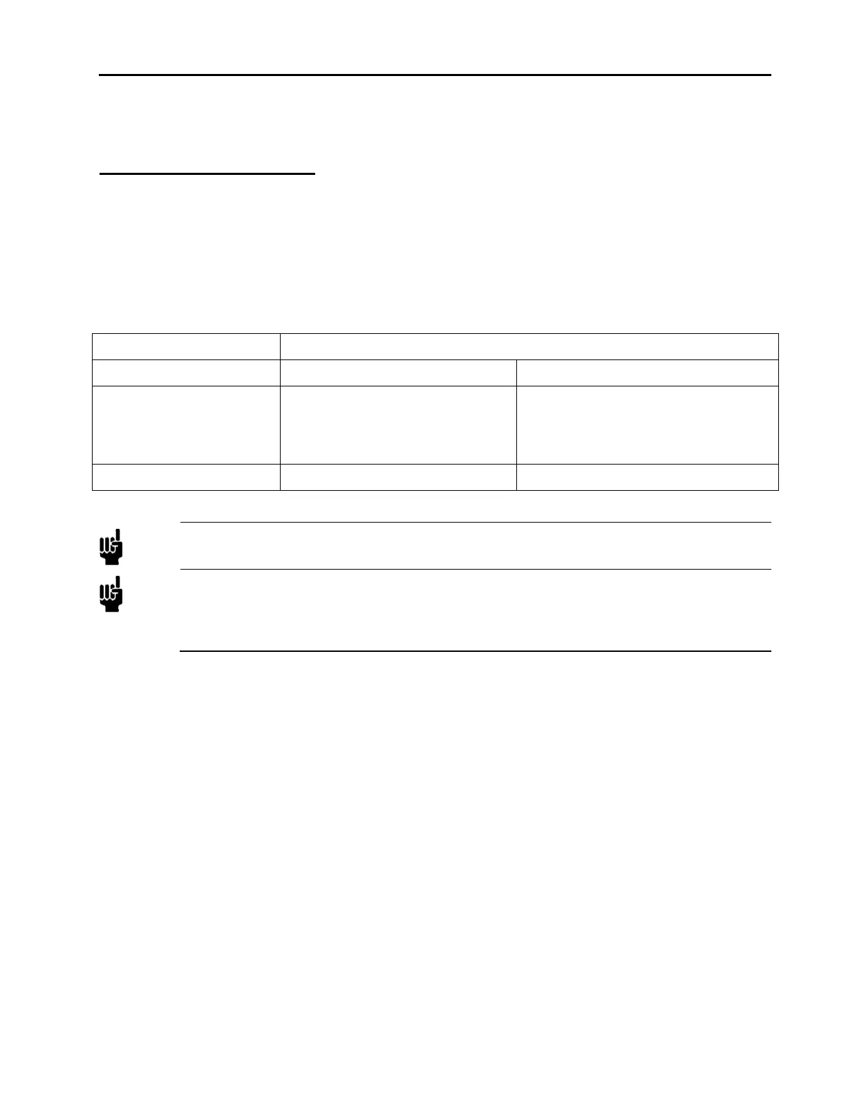
use. MKS offers a variety of interface cables, listed in Table 12, page 27.
Table 7: MKS Interface Cables
Power Supply End
MFC End 15-Pin Type “D” Flying Leads
15-pin Type D analog CB147-1
CB259-5
CB259-6
9-pin Type D analog CB147-12 Not Available
Note
An overall metal braided, shielded cable, properly grounded at both ends, is required to meet CE
Mark specifications.
Note
To order an overall metal, braided, shielded cable, add an “S”. after the cable type designation.
For example, to order a standard connection cable to connect the MFC to a power supply with a
15-pin Type .D. connector, use part number CB259-5; for an overall metal braided, shielded
cable use part number CB259S-5.
Generic Shielded Cable Description
MKS offers a full line of cables for most MKS equipment. Should you choose to manufacture your own
cables, follow the guidelines listed below:
1. The cable must have an overall metal braided shield, covering all wires. Neither aluminum foil nor spiral
shielding will be as effective; using either may nullify regulatory compliance.
2. The connectors must have a metal case with direct contact to the cable shield on the whole circumference
of the cable. The inductance of a flying lead or wire from the shield to the connector will seriously degrade
the shields effectiveness. Ground the shield to the connector before its internal wires exit.
3. With very few exceptions, the connector(s) must make good contact to the device’s case (ground). Good
contact is about 0.01 ohms and the ground should surround all wires. Contact to ground at just one point may
not suffice.
4. For shielded cables with flying leads at one or both ends; it is important to ground the shield at each such
end before the wires exit. Make this ground with absolute minimum length. (A ¼ inch piece of #22 wire may
be undesirably long since it has approximately 5 nH of inductance, equivalent to 31 ohms at 1000 MHz).
After picking up the braid ground, keep wires and braid flat against the case. With very few exceptions,
grounded metal covers are not required over terminal strips. If one is required, it will be stated in the
Declaration of Conformity.