Do you have a question about the MLC LC100 and is the answer not in the manual?
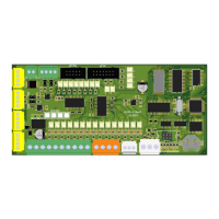
Central control system plate of LC100 system for processing input/output.
Input/output unit for elevator cabin, powered via CAN/power connector.
Input/output unit for elevator cabin, powered via CAN/power connector.
Input/output unit for elevator cabin, powered via CAN/power connector.
Safety board to connect safety circuit elements, transfer info to LC100-C.
Safety board to connect safety circuit elements, transfer info to LC100-C.
Input/output unit for cabin call processing, CAN communication.
Input/output unit for cabin call processing, CAN communication.
Input/output unit for landing and cabin call processing, CAN communication.
Input/output unit for landing/cabin call processing, CAN communication.
Input/output unit for landing/cabin call processing, CAN communication.
Input/output unit for landing/cabin call processing, CAN communication.
General system settings, number of floors, elevators, evacuation.
Defines call processing types for single and collective systems.
Defines main drive types, nominal speeds, and stopping parameters.
Configures cabin and landing door types, opening times, and behavior.
Sets elevator positioning types, learning drive, and decelerating zones.
Sets stopping delay for each floor for leveling adjustment.
Configures car fan, car light, shaft light, and programmable relays.
Sets PTC resistance, travel times, and temperature limits.
Programs input and output pins of LC100 boards.
| Type | Programmable Logic Controller (PLC) |
|---|---|
| Memory | 8KB program memory, 4KB data memory |
| Communication | RS-232, RS-485 |
| Power Supply | 24V DC |
| Operating Temperature | 0°C to 50°C |