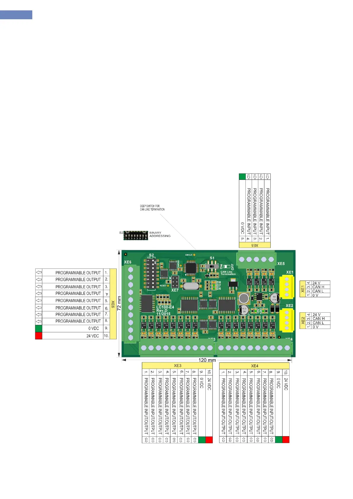
2.11 LC100-E4 cabin I/O board
LC100-E4 board of the system is used as input / output unit. The main purpose of the board is for landing and
cabin call processing and for inputs/outputs. It consists of CAN communication connector XE1 and XE2,and connector
XE3 and XE4 with I / O pins and XE6 output connector and XE5 input connector.
The system can have 4 LC100-E4 boards addresses LC100-E0, E1, E2, E3 (must be enabled with A-10
parameter)
Addressing LC100-E4 board is performed by S2 deep switch (binary addressing), adresses are given in the
ADRESSING TABLE.
All I / O pins are programmable and are equipped with LED indication to monitor the status of inputs / outputs.
XE4.7 XE4.8 pins and are used for managing matrix indicator if the pins do not havefunction.
Jumpers JP3 and JP4 are used to terminate the CAN bus communication.
Input supply is 24VDC and it is powered through the CAN-power conector.
Dimensions of board is 120x72mm, mounting is done on TS35 rail using a carrier plate.
Picture 9- LC100-E4 bord