2.12 LC100-E5 cabin I/O board
LC100-E5 board of the system is used as input / output unit. The main purpose of the board is for landing and
cabin call processing. It consists of CAN communication connector XE1 and XE2,and connector with I / O pins XE3
and XE4.
The system can have 8 LC100-E5 boards addresses LC100-E0, E1, E0(FC), E0(FD), E1(FC), E1(FD), LC100-
K(FC),K(FD)..
Addressing LC100-E5 board is performed by dip switches binary addressing.
All I / O pins are programmable and are equipped with LED indication to monitor the status of inputs / outputs.
XE4.7 XE4.8 pins and are used for managing matrix indicator if the pins do not havefunction.
S1 switch are used to terminate the CAN bus communication.
Input supply is 24VDC and it is powered through the CAN-power conector.
Dimensions is 171,5x42mm board, installation is done installing the spacers.
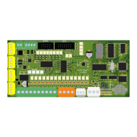
Cabin comands wireing diagram:
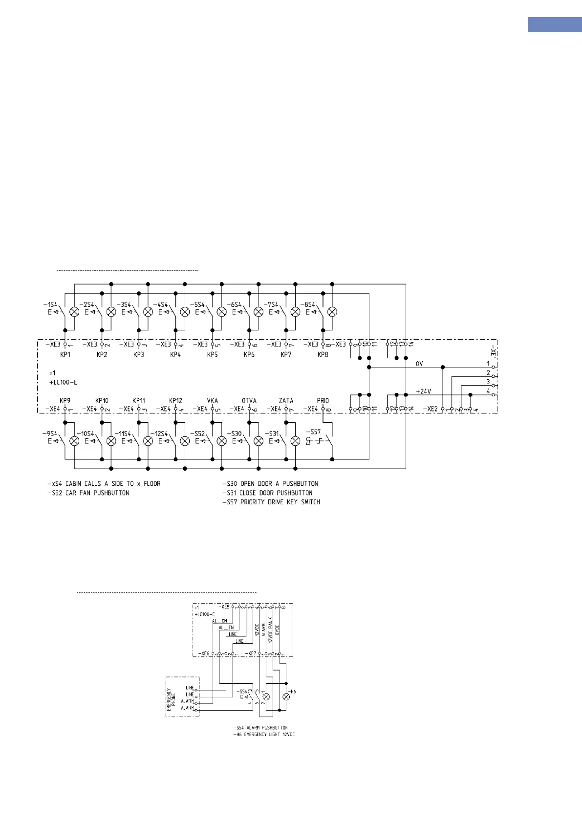
LC100-E5 board also contains connectors for connecting alarm push button, emergency phone and emergency
power supply in the cabin.
- XE6 connector for connecting a voice device
- XE7 connector for connecting alarm pushbutton.
- XE8 connector for connecting LC100-E5 with LC100-Z board.
Connection diagram for alarm pushbutton