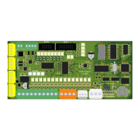
Upon entering error analysis menu, LC100-D searches the CAN bus for
connected LC100 modules. Modules must have firmware version 4.00 or
newer in order to be able to transfer their error counters.
After the search is finished, LC100-D will display a menu containing all
of the connected modules (image shows an example of LC100-M5 module,
addressed for 1. stop, elevator A and door A). Module can be selected by
pressing LEFT and RIGHT keys (provided that there is more than one module).
By pressing ENTER key, LC100-D will enter selected modules’ error counter
menu.
Error counter menu displays error counter values which can be listed
through by pressing UP and DOWN keys. There are 7 values in total:
1. REC – CANREC
2. TEC – CANTEC
3. Stuff – bit stuffing error counter
4. Form – form error counter
5. Ack – ACK error counter
6. Bit – bit error counter
7. CRC – CRC error counter
Error types description can be found in the CAN bus specification.
CANREC and CANTEC counters display the current values of the CAN
counters from the modules’ CAN controller. Other counters accumulate values
until they are reset to zero by pressing REEST key.
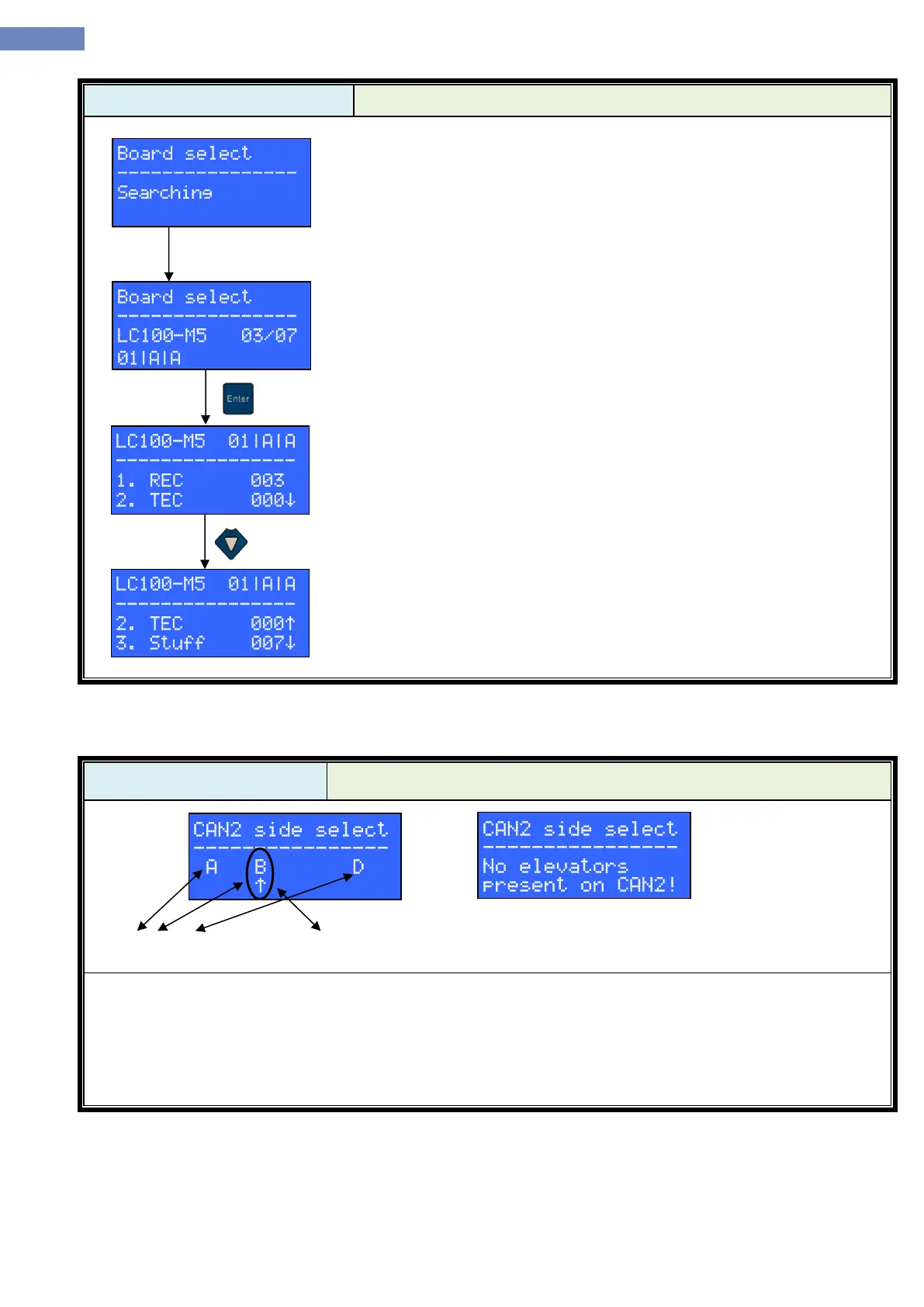
- CAN2 side select menu can be used to connect LC100-D to an elevator via CAN2 bus.
- Menu shows elevators present on the CAN2 bus in real time
- If there are no elevators connected to the CAN2 bus message like the one on the right picture is displayed.
- Elevator can be selected by pressing LEFT and RIGHT keys.
- To connect to the selected elevator user has to press the ENTER key. After the key press, LC100-D will exit
the CAN2 side menu and display chosen elevator’s main menu.