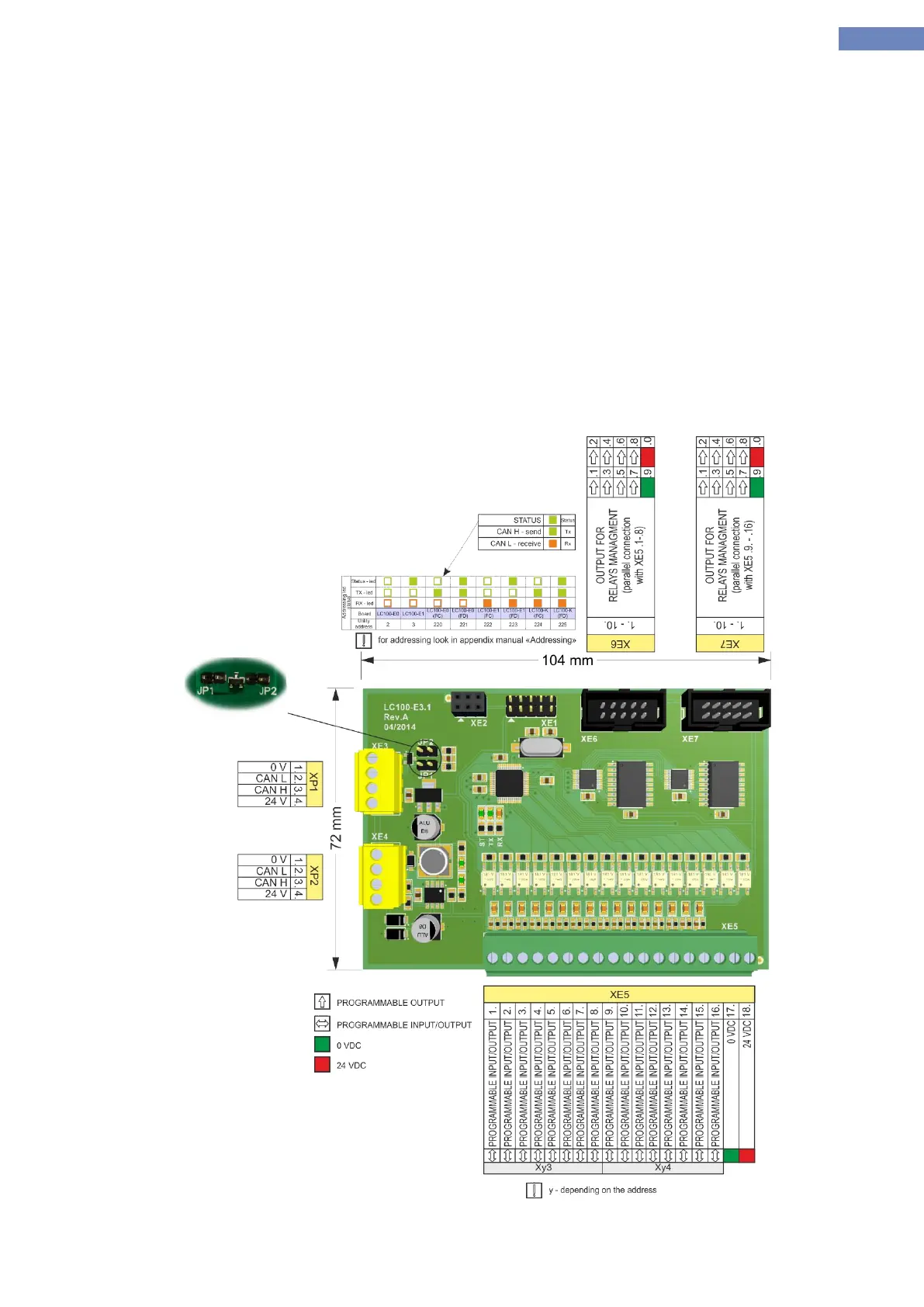
2.10 LC100-E3.1 cabin I/O board
LC100-E3.1 board of the system is used as input / output unit. The main purpose of the board is for landing and
cabin call processing. It consists of CAN communication connector XE3 and XE4,and connector with I /
O pins and XE5 with parallel connection to XE6 and XE7 connector for managment relays.
The system can have 8 LC100-E3.1 boards addresses LC100-E0, E1, E0(FC), E0(FD), E1(FC), E1(FD), LC100-
K(FC),K(FD)..
Addressing LC100-E3.1 board is performed by software addressing menu
All I / O pins are programmable and are equipped with LED indication to monitor the status of inputs / outputs.
XE4.7 XE4.8 pins and are used for managing matrix indicator if the pins do not havefunction.
Jumpers JP1 and JP2 are used to terminate the CAN bus communication.
Input supply is 24VDC and it is powered through the CAN-power conector.
Dimensions of board is 104x72mm, mounting is done on TS35 rail using a carrier plate.
Picture 8- LC100-E3.1 bord