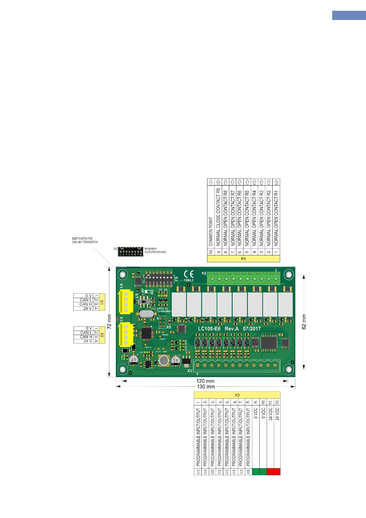
2.13 LC100-E6 cabin/landing I/O board
LC100-E6 board of the system is used as input / output unit. The main purpose of the board is for landing and
cabin call and output for driving display. It consists of CAN communication connector X1 and X2, and connector X3 I /
O pins and X4 output connector through relays.
The system can have 8 LC100-E4 boards addresses LC100-E0, E1, E2, E3, E4, E5, E6, E7 (must be enabled
with A-7 parameter)
Addressing LC100-E6 board is performed by dip switches binary addressing.
X3 I / O pins are programmable and are equipped with LED indication to monitor the status of inputs / outputs.
X4 pins are only have output programmable and they are equipped with LED indication to monitor the status of
outputs.
S1 switch are used to terminate the CAN bus communication.
Input supply is 24VDC and it is powered through the CAN-power conector.
Dimensions is 171,5x42mm board, installation is done installing the spacers.
Picture 10- LC100-E6 board