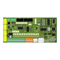
Choosing the positioning type:
1 – Positioning type for one speed elevator. For positioning type 1 referent
switches are used and stopping switch is used. Elevator is driving with one
speed, floors are counted when passing through stop switch according to the
driving direction.
2 – Positioning type with two switches for counting. There are also two referent switches and stopping switch.
Elevator counts the floors +1 when pasing counting up switch and -1 when passing by the counting down switch.
Counting switches are also the slowing down point for the middle floors while for the end floors slowing down point
is the referent switch.
3 – Possitioning type with bistabile counting switch. There are also two referent switches and stopping switch.
Elevator counts the floors when passing by counting switch according to the travelling direction. Counting switch is
also the slowing down point for the middle floors while for the end floors slowing down point is the referent switch.
4 – Positioning type with inductive switch. There are also two referent switches and stopping switch. Elevator
countc the floors accordint to the traveling direction and the number of the impulses. Slowing down point for the final
floors are referent switches while for middle floors slowing down point is the same impulse numbers as for the final
floors. When using frequency regulator on CAN bus impulses are taken from the motor encoder.
5 – Positioning type with inductive switch and two nominal speeds. There are also two referent switches for
nominal speed, two referent switches for lower speed and stopping switch. First drive elevator goes with the lower
speed C-07 and slows down while passing the lower referent switch FI-251 or FI-253. Driving betwen two next floors
is always done with lower speed C-07. Driving two or more floor distances elevator is driving with nominal speed C-
03.
If the relevelling (C-18=1 or 2) or preopening the doors (D-28=1) is activated then there are two stopping switches:
stopping UP (FI-256) and stopping DOWN (FI-257), and one switch for door zone (FI-258).
If there is no releveling or preopening the doors activated one stopping switch is used. It is connected to input with
function stopping UP (FI-256) and it is used for stopping in both direction.
Connecting the positioning switches and magnets position in the shaft is explained in appendix POSITIONING.
6 – Absolute positioning system is an exclusive and innovative solution that provides absolute positioning
down to +/-1 mm. An absolute positioning system shall determine the absolute position and velocity of the elevator
car as it transits the histway by reading fixed installed code tape in the hoistway using an absolute encoder.
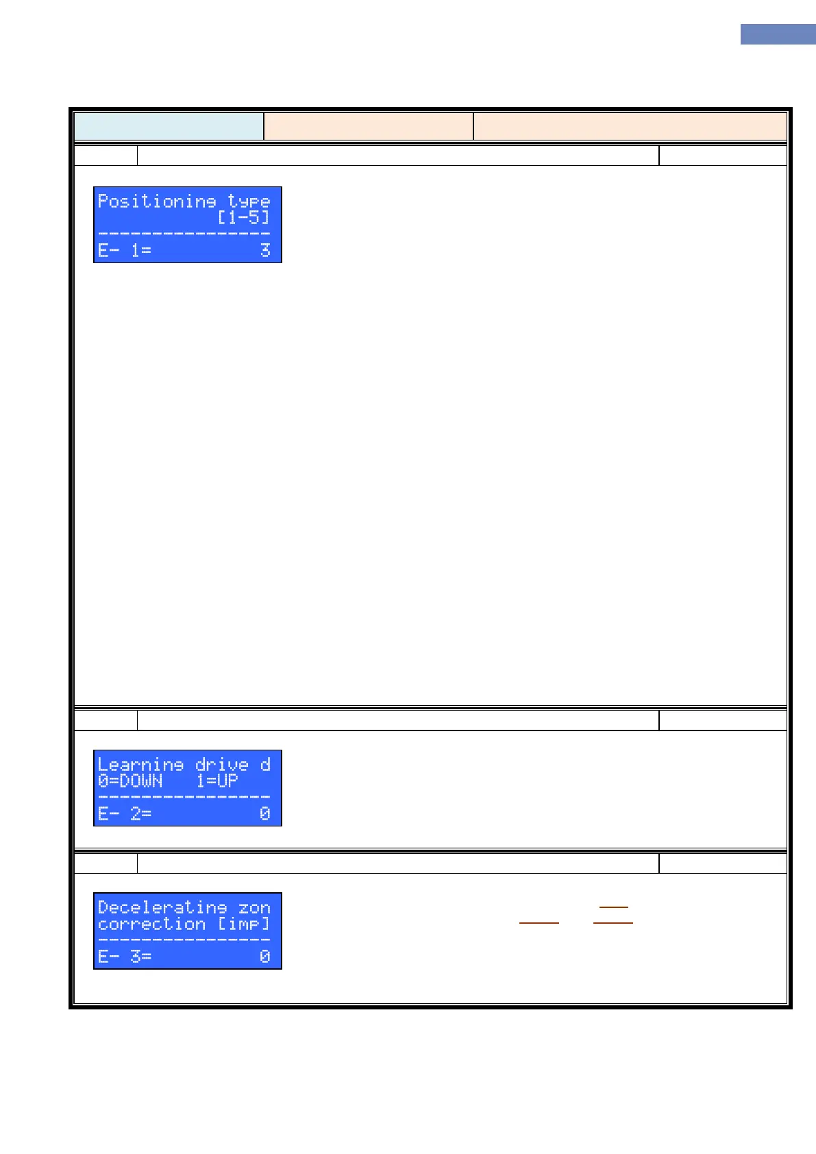
Choosing the direction for the learning drive. It is possible to chose direction
for the possitioning type E-01=1, 2 i 3. While when using positioning type 4 or
5 parameter is not in use.
0 – Learning drive is in direction UP
1 – Learning drive is in direction DOWN.
Parameter is active when using positioning type E-01=5 if there are no referent
switches inputs defined (functions FI-251 and FI-253). Decelerating zone for
nominal speed is defined as a sum of impulses for lower speed zone and this
parameter. When using this positioning type 5 subtype choosing the speed for
the drive is calculated with the floor to floor distance and decelerating zone
calculated by measurement and this parameter. This way it is possible that the
one floor distance is driven by lower or the nominal speed.