Contents
1. General ......................................................................................................................................4
2. LC100 boards description ......................................................................................................5
2.1 LC100-C main control unit ..............................................................................................5
2.2 LC100-K cabin I/O board ................................................................................................8
2.3 LC100-K2 cabin I/O board ..............................................................................................9
2.4 LC100-K3 cabin I/O board ............................................................................................10
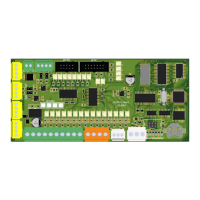
2.5 LC100-S safety circuit board ........................................................................................11
2.6 LC100-SR safety circuit board .....................................................................................16
2.7 LC100-E input-output unit for cabin calls ...................................................................17
2.8 LC100-E2 in/out board ..................................................................................................19
2.9 LC100-E3 cabin I/O board ............................................................................................21
2.10 LC100-E3.1 cabin I/O board .....................................................................................23
2.11 LC100-E4 cabin I/O board ........................................................................................24
2.12 LC100-E5 cabin I/O board ........................................................................................25
2.13 LC100-E6 cabin/landing I/O board ..........................................................................27
2.14 LC100-F in/out board .................................................................................................28
2.15 LC100-D control terminal ..........................................................................................29
2.16 LC100-D2 control terminal ........................................................................................30
2.17 LC100-Z cabin connection board .............................................................................31
2.18 LC100-R relay board with 4 relays ..........................................................................34
2.19 LC100-T relay board with 8 relays ...........................................................................35
2.20 LC100-I IN/OUT board ...............................................................................................36
2.21 Boards for landing calls and signalization ..............................................................38
2.21.1 LC100-M5 dot matrix display ................................................................................38
2.21.3 LC100-M7 segment display ..................................................................................40
2.22 Adressing the landing call units (LC100-M boards) ..............................................46
2.23 LC100-J input/output board ......................................................................................47
2.24 LC100-V load measurement board .........................................................................49
2.25 LC100-V2 load measurement board .......................................................................50
2.26 LC100-B CAN bridge board ......................................................................................51
2.27 LC100-VFD - CAN bridge bord, relay output, phase control bord ......................52
2.28 LC100-H CAN connection board .............................................................................53
2.29 LC100-GSM emergency voice call ..........................................................................54
2.30 LC100-HF handsfree voice communication ...........................................................55
3. Managment with LC100-D terminal ....................................................................................56
3.1 Basic view ............................................................................................................................56
3.1.1 Basic elevator state.....................................................................................................57
3.1.3 Display of current elevator station ............................................................................57
3.1.4 Safety line and drive display ......................................................................................58
3.1.5 Active delays and errors display ...............................................................................59
3.2 Menu structure ....................................................................................................................69
3.2.1 Statistics .......................................................................................................................70
4. Parameters .............................................................................................................................77
4.1 General - Type A ............................................................................................................78
4.2 Call processing – Type B ..............................................................................................80
4.3 Main drive - Type C ........................................................................................................84