10/05 AWB8230-1541GB
The network protocol
155
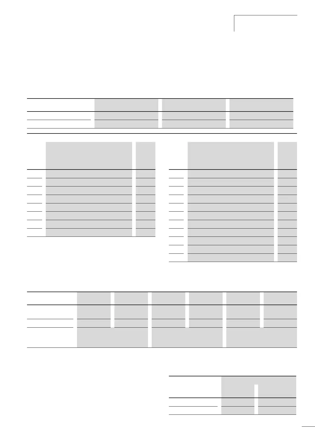
Reading the holding registers [03
hex
]
This function reads the content of a series of consecutive holding
registers with specified register addresses.
Example:
Reading three set parameters of a frequency inverter DF51 with
slave address 5 and the following content:
The reply record looks as follows:
If the read register status command cannot be run correctly, an
exception message is generated (a page 160).
Writing to coil [05
hex
]
This function writes data to a single coil. You can change the coil’s
status as follows:
DF51 command d001 (N) d002 (N-1) d003 (N-2)
Register number 1002
hex
1003
hex
1003
hex
Messages Output frequency 50 Hz Output current 0.13 A Clockwise rotating field
Request: Answer:
No.
Name Exampl
e
No. Name Exampl
e
hex hex
1 Slave address (broadcast disabled) 05 1 Slave address 05
2 Function code 03 2 Function code 03
3 Register start number (High byte) 10 3 Data length (in bytes)
1)
06
4
Register start number (Low byte) 02 4 Register start number (High byte) 01
5 Number of holding register (High byte) 00 5 Register start number (Low byte) F4
6 Number of holding register (Low byte) 03 6 Register start number + 1 (High byte) 00
7 CRC-16 (High byte) CRC 7 Register start number +1 (Low byte) 32
8 CRC-16 (Low byte) CRC 8 Register start number + 2 (High byte) 00
9 Register start number +2 (Low byte) 01
10 CRC-16 (High byte) CRC
11 CRC-16 (Low byte) CRC
1) Number of data bytes needed for a response to the request; here
6 bytes to return the content of three holding registers.
Response memory 4 5 6 7 8 9
Register number + 0
(High byte)
+ 0
(Low byte)
+ 1
(High byte)
+ 1
(Low byte)
+ 2
(High byte)
+ 2
(Low byte)
Register status 01
hex
F4
hex
00
hex
32
hex
00
hex
01
hex
Messages Output frequency 50 Hz Output current 0.13 A (5 % of 2.6 A) Direction of rotating field
• 01 = clockwise
• 02 = anticlockwise
Data Coil status
Off a On On a Off
Change data (High byte) FF
hex
00
hex
Change data (Low byte) 00
hex
00
hex