10/05 AWB8230-1541GB
Motor control
77
Start signal input
Start signal
By default the start signal is triggered through the inputs
configured as FWD (control signal terminal 1) and REV (control
signal terminal 2).
Clockwise rotating field (FWD)
When you activate the digital input configured as FWD (forward)
input, the frequency in phase sequence U-V-W is applied at the
DF51’s output. If connected accordingly, the motor then starts up
in a clockwise direction. When the input is deactivated, the motor
is decelerated.
Anticlockwise rotating field (REV)
When the digital input configured as REV (reverse) is activated, the
motor starts up in an anticlockwise direction (W-V-U). When the
input is deactivated, the motor is decelerated.
If you activate the FWD and the REV input at the same time during
operation, the motor coasts to a halt.
Under PNU C001 to C005 or C201 to C205 (second parameter set)
you can assign the start signal to any digital input: 00 = FWD,
01 = REV.
Parameterizable digital inputs
Various functions can be assigned to terminals 1 to 5. Depending
on your requirements, you can configure these terminals as
follows:
• start signal anticlockwise rotating field (REV),
• selection inputs for various fixed frequencies (FF1 to FF4),
• reset input (RST),
•etc.
The terminal functions for programmable digital inputs 1 to 5 are
configured with PNU C001 to C005. i.e. with PNU C001, you
specify the function of digital input 1, with PNU C002 the function
of digital input 2, etc. Note, however, that you cannot assign the
same function to two inputs at the same time.
Programmable digital inputs 1 to 5 are configured by default as
make contacts. If, therefore, the function of an input terminal is to
be activated, the corresponding input must be closed (i.e. the input
terminal is, for example, connected to terminal P24). Deactivation
results in interruption of the input voltage (+24 V).
Table 22: Digital inputs 1 to 5
For a detailed description of the input functions, see the pages
listed in Table 23.
Warning!
If the supply voltage for the frequency inverter is applied
when the start signal is activated, the motor will start
immediately. Make sure that the start signal is not active
before the supply voltage is switched on.
Warning!
Note that, when the FWD/REV input is opened (inactive
condition when it has been configured as a N/O contact)
and the input is then reconfigured as N/C contact, the
motor may start immediately after the configuration.
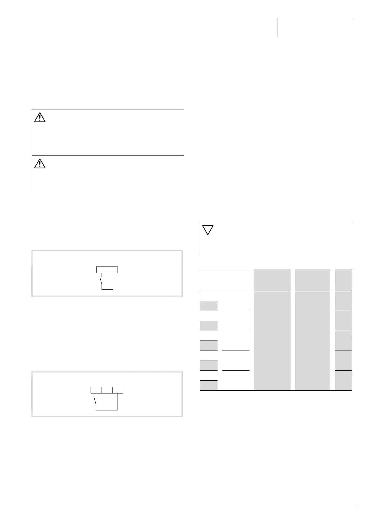
Figure 76: Digital input 1 configured as FWD
Figure 77: Digital input 2 configured as REV
FWD
P241
REV
P2412
Caution!
If an EEPROM error occurs, (fault message E08), all
parameters must be checked to ensure that they are
correct (especially the RST input).
PNU Terminal Adjustable in
RUN mode
Value DS
C001 1 – a table 23 00
C201
C002 2 01
C202
C003 3
02
C203
C004 4
03
C204
C005 5
18
C205