10/05 AWB8230-1541GB
Braking
125
Braking
Braking is the slowing down of a drive system to standstill or a
specific lower speed within a specified time. Braking can take
place mechanically (using a friction brake) or electrically (DC
braking or braking choppers).
The DF51 devices allow the following braking methods:
• Actuation of an external mechanical holding brake through
relay K1 (a section “Signalling relay K1 (terminals K11, K12,
K14)”, page 107) or a digital output (a section
“Parameterizable digital outputs”, page 105).
• DC braking: applying direct current to the three-phase motor
DC braking (DCB)
To activate DC braking for decelerating the motor, do the
following:
• Apply a stop signal (PNU A051 = 01) or
• activate the digital input configured as DB (a section “DC
braking (DCB)”page 125).
By applying a pulsed DC voltage to the motor stator, a braking
torque is induced in the rotor and acts against the rotation of the
motor. With DC braking, a high level of stopping and positioning
accuracy can be achieved.
Under PNU A051, define whether DC braking is to be activated
automatically when the frequency set under PNU A052 us reached
and/or when the DB input is activated.
Under PNU A052 enter the frequency at which DC braking is
activated when PNU A051 is 00.
Under PNU A053, enter the waiting time which is to elapse before
DC braking becomes active after activation of the DB input or
when the set startup frequency is reached.
Under PNU A054 enter the braking torque between 0 and 100 %.
In PNU A055, enter the DC braking duration.
Under PNU A056 specify the braking behaviour when the DB input
is active:
• 00: DC braking starts when the DB input is activated and ends
only when the time defined under PNU A055 has expired.
• 01: Braking starts as soon as the DB input is active and ends
when the DB input is deactivated.
DC braking can also be activated before motor acceleration, for
example in lifting and conveying applications (releasing the
mechanical holding brake) or with drives which are operated using
process variables, such as fans, pumps and compressors.
X Configure one of the digital inputs 1 to 5 as DB by entering the
value 07 under the corresponding PNU (C001 to C005).
X In PNU A053, enter a delay time t (a fig. 133) from 0 to 5.0 s,
which is to expire before DC braking takes effect after activation
of the DB input.
X Under PNU A054, set a braking force between 0 % and 100 %.
Figure 132:Digital input 1 configured as FWD (start/stop clockwise
rotating field), input 2 as REV (start/stop anticlockwise
rotating field) and input 5 as DB (DC braking)
DB
FWD
REV
P24125
Caution!
DC braking results in additional heating of the motor.You
should therefore configure the braking torque
(PNU A054) as low and the braking duration (PNU A055)
as short as possible.
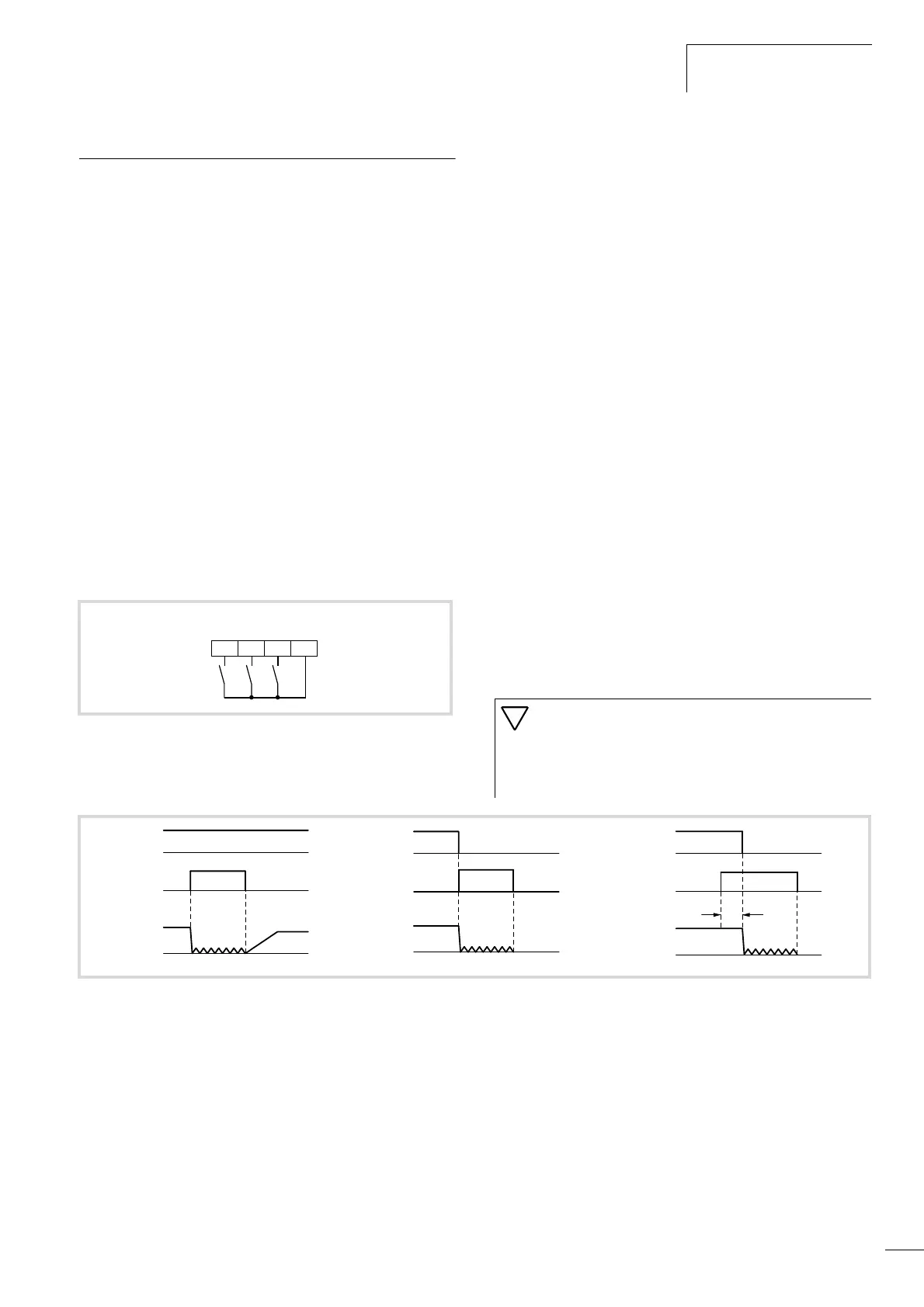
Figure 133:Function chart for DB (DC braking)
f
o
: Output frequency
t: Waiting time PNU A053
a Start signal through keypad
FWD/REV
DB
f
O
DB
f
O
a
DB
f
O
a
t