Setting parameters
10/05 AWB8230-1541GB
136
Activating and deactivating PID control (PID)
With a digital input configured as PID, PID control can be switched
on and off through control signal terminals. When you activate the
PID input, PID control is disabled. The frequency inverter then
works with its standard frequency control again.
X Configure one of the digital inputs 1 to 5 as PID by entering the
value 23 under the corresponding PNU (C001 to C005).
With the digital input configured as PIDC, the integral component
of the PID control can be reset. If the PIDC input is activated, the
integral component is reset to zero.
X Configure one of the digital inputs 1 to 5 as PIDC by entering
the value 24 under the corresponding PNU (C001 to C005).
PID system deviation (OD)
The PID system deviation (e) is the difference between reference
and actual value (process variable PV).
The digital output configured as OD is activated when PID control
is active (PNU A071 = 01) and a user-definable system deviation
(PNU C044) is exceeded.The OD output remains active as long as
this limit value is exceeded.
X To configure a parameterizable digital output (11 or 12) or
signalling relay K1 as OD, define the limit value under
PNU C044 above which the OD signal is activated.
X Configure one of the digital outputs (11, 12) as OD by entering
the value 04 under PNU C021 or C022, or under PNU C026 for
signalling relay K1.
h
This function is available only when PID control is active
(PNU A071 = 01).
h
Do not switch the PID controller on and off while the
frequency inverter is in RUN mode (RUN LED is lit).
h
The Activate/Disable PID Control function is optional. If
you want PID control to be active all the time, you only
need to set PNU A071 to 01.
h
Do not reset the integral component of the PID controller
while the frequency inverter is in RUN mode (RUN LED is
lit), as this can cause overcurrent tripping and rapid
deceleration, resulting in unpredictable operating states.
Figure 140:Digital input 1 configured as FWD (start/stop clockwise
operation), input 2 as PID (activate/deactivate switch PID
control) and input 3 as PIDC (reset integral component).
PIDC
FWD
PID
P24123
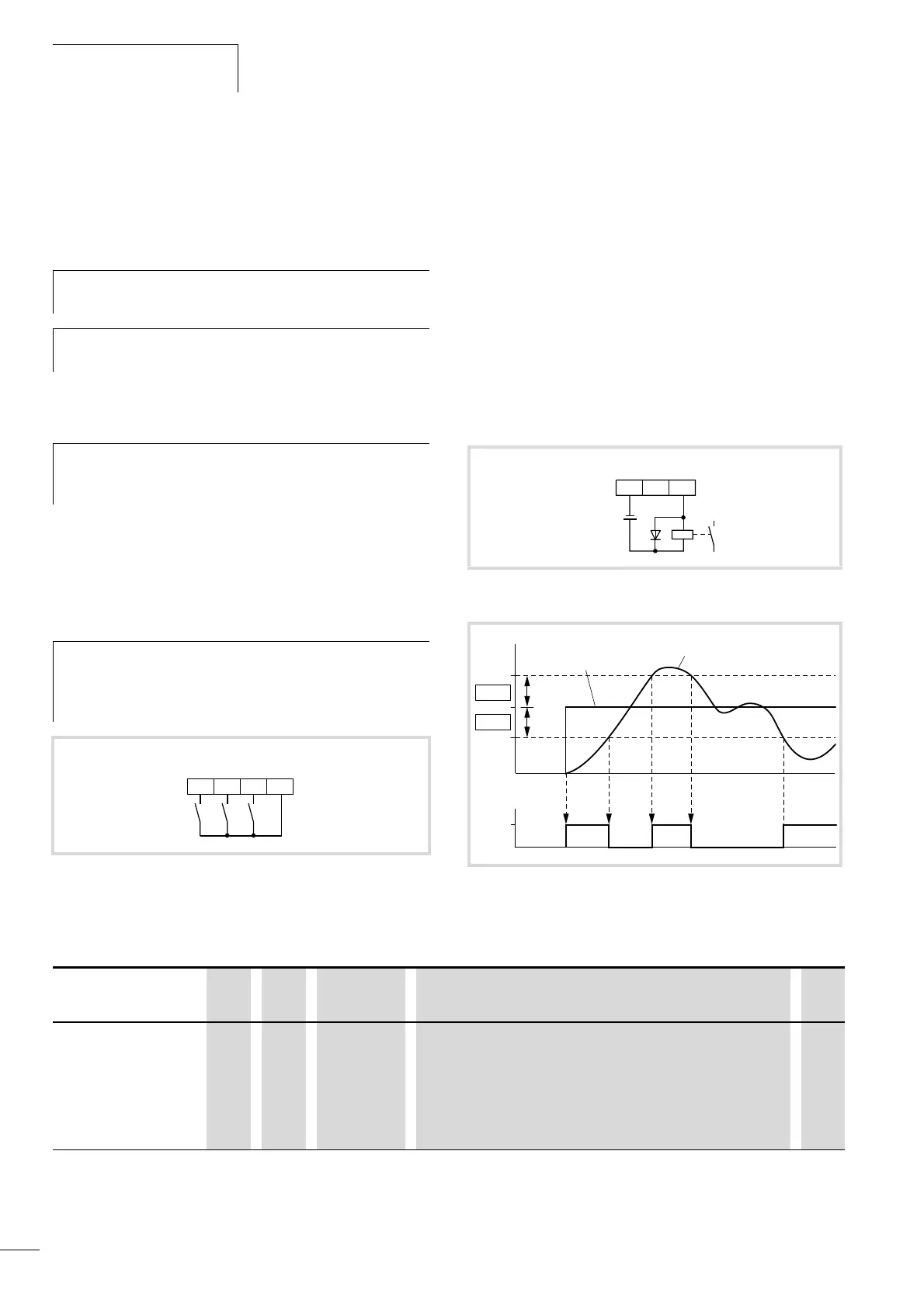
Figure 141:Digital output 11 configured as OD “PID system deviation”
Figure 142:Function chart for OD (PID system deviation)
a Reference value
b Actual value
OD
24 V
50 mA
1112CM2
OD
a
b
C044
C044
PNU Name RUN b031
= 10
Value Function DS
C044 Output
function:
Signalling
threshold,
maximum PID
control
deviation
– j 0 – 100 % If the deviation between the setpoint and actual value exceeds the
value entered here when PID control is active (PNU A071 = 01), the OD
signal is activated.
3.0