10/05 AWB8230-1541GB
Actual value and status signals
105
Parameterizable digital outputs
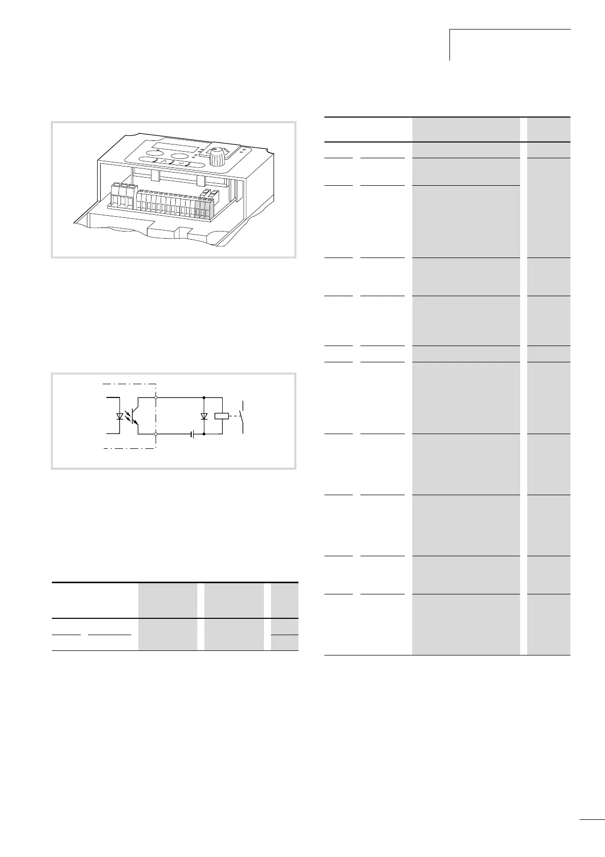
Configurable digital outputs 11 and 12 are open collector
transistor outputs (a fig. 106), to which you can connect, for
example, relays (such as ETS4-VS3, Order No. 083094). These
outputs can both be used for various functions, for example to
signal when a determined reference frequency is reached or when
a fault occurs.
Terminal CM2 is the common reference potential for digital
outputs 11 and 12. CM2 can be connected to 0 V in sink-type logic
and to +24 V in source-type logic (a fig. 49, page 48).
Table 31: Digital outputs 11 and 12
For a detailed description of the output functions, see the pages
listed in Table 32.
Table 32: Functions of the digital outputs
Figure 105:Digital outputs 11 and 12, CM2
Figure 106:Digital output (sink-type)
Transistor output: maximum 27 V H, 50 mA
PNU Terminal
Adjustable in
RUN mode
Value DS
C021 11 – a table 32 01
C022 12 00
I
O
K12 K14 K11
AM
H
O
OI
L
L 5
4 3 2 1
P24
CM2
12 11
F 27 V H, 50 mA
11, 12
CM2
24 V
– +
Value Function Description a page
00 RUN RUN: In operation 109
01 FA1 FA1: Frequency reference
value reached
110
02 FA2
FA2: Frequency signal –
output frequency exceeds
value in PNU C042 (during
acceleration ramp) or
PNU C043 (during
deceleration ramp)
03 OL
OL: Overload warning – motor
current exceeds value in
PNU C041.
114
04 OD
OD: PID control –
reference/actual value
difference exceeds signalling
threshold set with PNU C044.
136
05 AL
AL: Fault – fault/alarm signal 121
06 Dc Dc: Warning – Reference value
at input O (0 to +10 V) lower
than value in PNU b082 or
current signal at input OI
below 4 mA. (reference value
signal interrupted)
07 FBV FBV: PID control – Actual
value monitoring (PV) signal
on breach of limit values
PNU C052/C053. (actual
value signal interrupted)
08 NDc NDc: Fault/warning
dependent on PNU C077 –
communication watchdog
timer has expired:
communications are faulty.
09 LOG LOG: Shows result of logic link
performed through
PNU C143. (High, Low)
10 ODc ODc: Fault/warning –
communication overload or
interrupted (with optional
DE51-NET-CAN,
DE51-NET-DP). (overload)