10/05 AWB8230-1541GB
Keypad
55
Keypad
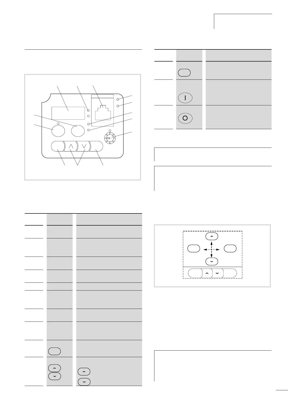
The illustration below shows the elements of the DF51’s built-in
keypad.
Table 17: Explanation of the operation and display elements
Navigation within the menu
Press the PRG key to change to parameterization mode.
In parameterization mode, the keys have the following functions:
• The PRG key changes the display between main menu,
parameter and value range.
• The Up and Down arrow keys scroll through the individual
parameters, digits and functions.
• The ENTER key saves any changed settings.
Figure 55: Keypad view
For an explanation of each of the elements, see Table 17.
Number Name Explanation
a Four-digit
digital display
Display for frequency, motor current,
PNU, fault messages, etc.
b LED: Hz or A Display in a: output frequency (Hz)
a PNU d001 (DS) or output
current (A) a PNU d002.
c
RS 485 Serial interfaces RS 485 and
Modbus RT
d
POWER LED LED is lit when the frequency inverter
has power.
e
LED ALARM LED is lit when a fault signal occurs.
f
RUN LED LED lit in RUN mode when the
frequency inverter is ready for operation
or is in operation.
g
PRG LED LED is lit when the input/change of
parameter mode is active.
h Potentiometer
and LED
Frequency reference value setting
LED is lit when the potentiometer is
enabled a PNU A001 = 00.
i
ENTER key
The key is used for saving entered or
changed parameters.
j
Arrow keys
Selecting functions, changing numeric
values
Increase
Reduce
ab
l
kj i
m
d
c
e
f
g
h
A
RUN
PRG
Hz
PRG
ENTER
IO
POWER
ALARM
ENTER
k PRG key
Programming mode. Selection and
activation of the specified parameter
(PNU)
l Start key and
LED
Motor start with the selected direction;
disabled by default.
LED is lit when the key is enabled
a PNUA002=02
m
STOP key
Stop the running motor and
acknowledge a fault signal (RST =
Reset). Enabled by default, even when
actuation is through terminals.
DS = default setting
PNU = parameter number
h
The STOP pushbutton m is active in all operating modes
(a page 140PNU b087).
h
If frequency inverter DF51 is connected to a field bus
(CANopen, PROFIBUS DP) or an external keypad through
the serial interface, the keys are disabled, except for the
STOP key.
Figure 56: Navigation within the menu
h
The changes you make remain saved in (non-retentive
memory) as long as the frequency inverterDF51 is
supplied with power (POWER LED is lit). The changes are
saved permanently (in EEPROM) only when you press the
ENTER key.
Number Name Explanation
PRG
PRG PRG
PRG
ENTER