Setting parameters
10/05 AWB8230-1541GB
78
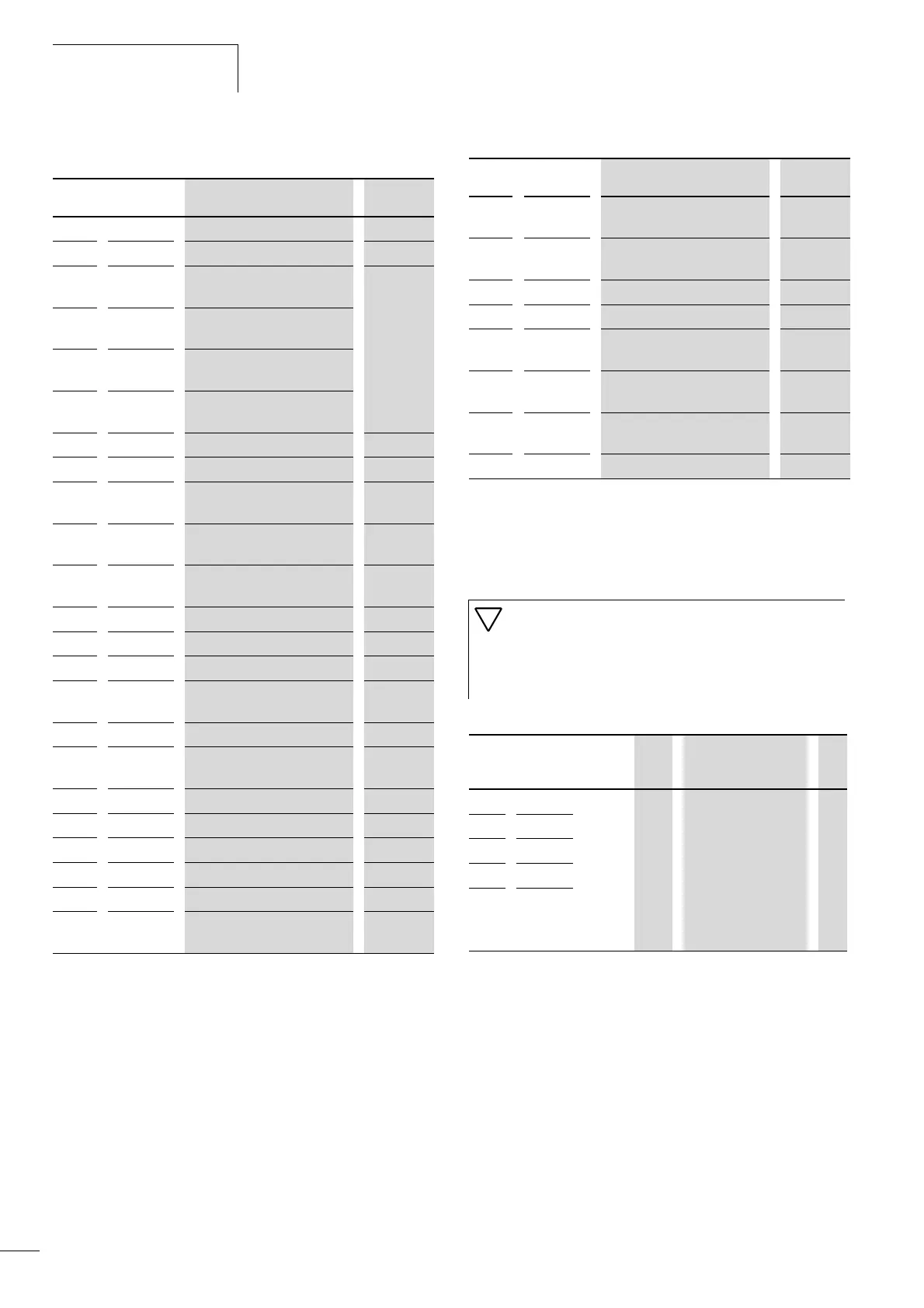
Table 23: Function of the digital inputs
If required, the digital inputs can be configured as break (NC)
contacts. To do this, enter 01 under PNU C011 to C015
(corresponding to digital inputs 1 to 5). An exception applies only
to inputs configured as RST (reset) or PTC (PTC thermistor input).
These inputs can be operated only as make (NO) contacts.
Table 24: Configuring digital inputs as break contacts
Value Function
Description a page
00 FWD Start/stop clockwise 77
01 REV Start/stop anticlockwise 77
02 CF1 Binary input 1 (LSB) (fixed
frequency 1)
97
03 CF2 Binary input 2 (fixed
frequency 2)
04 CF3
Binary input 3 (fixed
frequency 3)
05 CF4 Binary input 4 (MSB) (fixed
frequency 4)
06 JOG Jog mode 101
07 DB
DC braking 125
08 SET
Selection of second parameter
set
83
09 2CH Second acceleration and
deceleration time
93
11 FRS
Controller inhibit and coasting
to halt
79
12 EXT External fault 121
13 USP Unattended start protection 124
15 SFT Parameter protection 143
16 AT Reference input through
current
88
18 RST Fault signal reset 122
19 PTC PTC thermistor input (digital
input 5 only)
116
20 STA Start signal (3-wire) 80
21 STP Stop signal (3-wire) 80
22 F/R Direction of rotation (3-wire) 80
23 PID
Activation of PID control 136
24 PIDC
Reset integral component 136
27 UP Acceleration (motor
potentiometer)
99
28 DWN Deceleration (motor
potentiometer)
99
29 UDC Reset frequency (motor
potentiometer)
99
31 OPE Keypad 81
50 ADD Add frequency offset 128
51 F-TM Control signal terminals mode
enabled
81
52 RDY Inverter, reduce response time
to control signals
142
53 SP-SET
Second parameter set with
special functions
83
255 – Not used –
Caution!
If you reconfigure digital inputs set up as FWD or REV as
break contacts (the default setting is as a make contact),
the motor starts immediately. They should not be
reconfigured as break contacts if no motor is connected.
PNU Termina
l
Valu
e
RUN Function DS
C011 1 00 or
01
– 00: High signal causes
switch or activation of
the function (NO =
normally open).
01: Low signal causes
switching or
activation of the
function (NC =
normally closed).
00
C012 2
C013 3
C014 4
C015 5
Value Function
Description a page