Chapter 7 Assembly of the Devices
170
7.15 Connection of Each Cable
Connect the cable for each device.
Cautions for connecting cables
• Be sure to turn off the power to the microscope and peripheral units before connecting any cables.
• Fully and securely insert the end of the cables to the connectors to connect the cables.
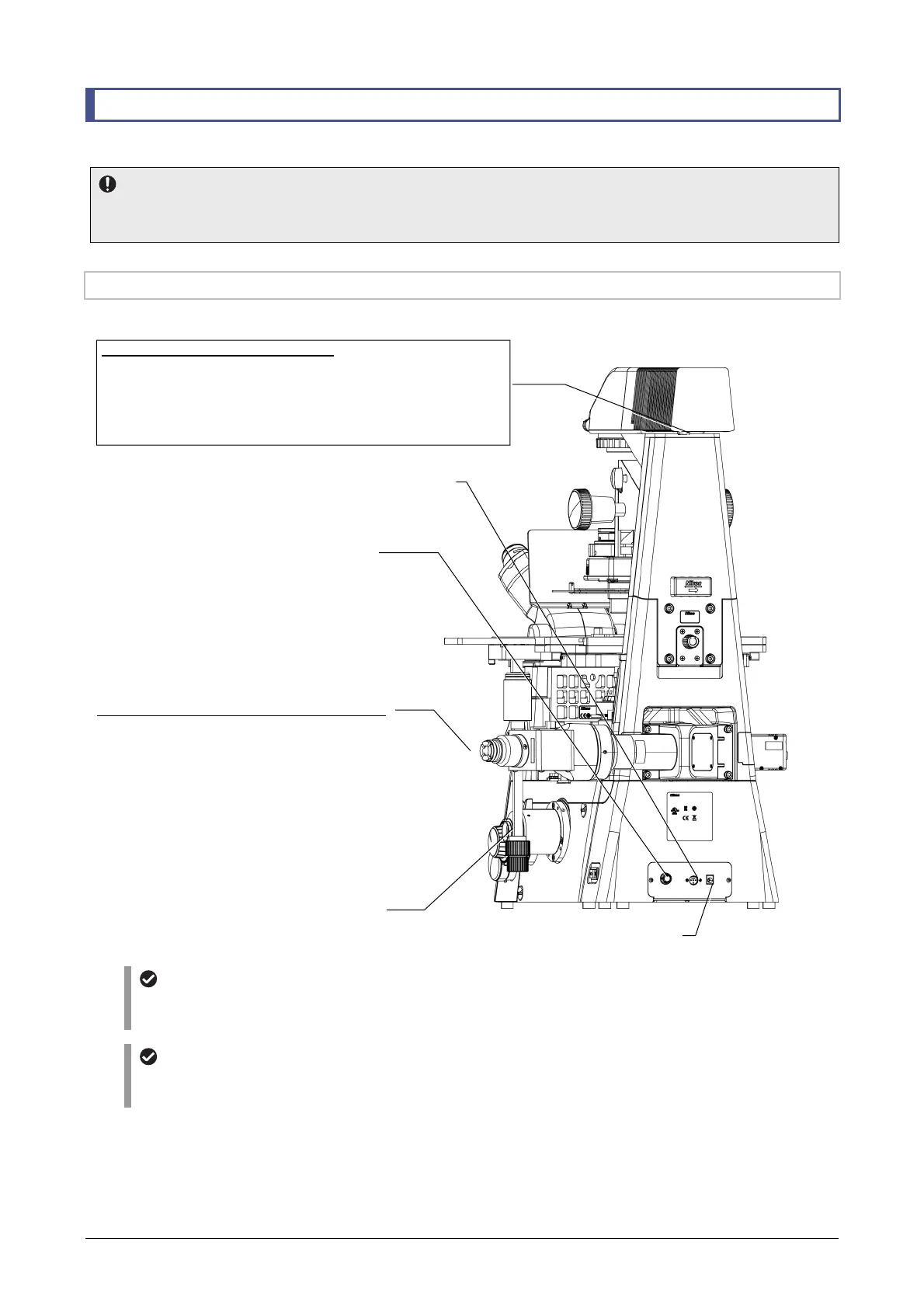
7.15.1 Position of Each Connector
The position of each connector is as follows:
Rear surface of the Ti2-U main body
Mounting a fluorescence LED illumination system
For details on how to mount a fluorescence LED illumination system, see the instruction manual for the
D-LEDI Fluorescence LED Illumination System.
Mounting a power supply for dia-illumination
For details on how to mount a power supply for dia-illumination when using a D-LH/LC precentered
lamphouse, see the instruction manual for the TI-PS100W/A power supply unit.
Side port
(A camera device can be
attached here.)
Diascopic illumination-related connectors
•
When a TI2-D-LHLED LED lamphouse for dia-illumination is used:
Connect to the LAMP CTRL connector of the rear surface connector box.
•
When a D-LH/LC precentered lamphouse is used:
Connect to the 12 VDC output connector of the diascopic illumination
power supply.
Connectors related to epi-fluorescence attachments
Connected to the D-LEDI fluorescence LED illumination
system
LAMP CTRL
•
When a TI2-D-LHLED LED lamphouse for
dia-illumination is used:
Connected to a cable from the LED lamphouse for
dia-illumination
•
When a D-LH/LC precentered lamphouse is used:
Connected to the
EXTERNAL
connector on the
power supply for dia-illumination with an
S-TI2-100WRC remote cable for 100-W
lamphouse
INTERLOCK
Required in a laser system
DC12VIN
Connected to the specified AC adapter