TFE-4RV-1 Company Confidential
Troubleshooting Nokia Customer Care
Page 6-30 Copyright © 2005 Nokia Corporation Issue 2.0 Mar/2005
Company Confidential
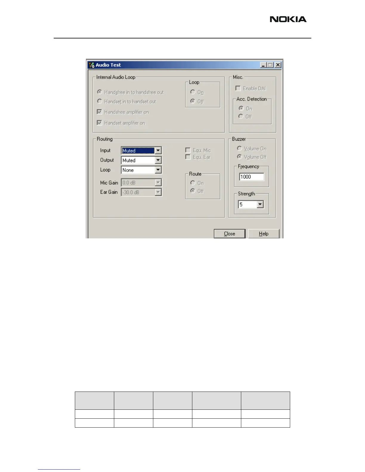
Figure 11: Audio-Test
Perform the Test:
Basic Setup:
A Loop is switched internally to send the HF-Mic signal to the HF-Speaker and in a sec-
ond step the HDMIC signal to the HD Speaker. Blowing into the microphone shall be
hearable in the speaker. By activating the hands free speaker mute, the Loop has to be
opened (no signal goes through). When the headset is connected, blowing into handset
microphone shall be hearable at the handset speaker. By activating the handset speaker
mute, the Loop has to be opened (no signal goes through).
Extended Setup:
In this case, a Loop is switched internally to send the HF-Mic signal to the HF-Speaker
and in second step the HD-MIC to the HD-Speaker. The frequence of 1000Hz has to be
tested. Additionally the distortion has to be checked. By activating the hands free
speaker mute or the handset speaker mute option within the Digital I/O tests the regard-
ing Loop has to be open.
The Bias Voltage of the HF-MIC is to be measured with Voltmeter (<>5V).
MIC-Path Frequency
Generator
Voltage
Low
Limit
Upper
Limit
HDMIC 1000 30mV. 440mV (30dB) 705mV (40dB)
HFMIC 1000 50mV 1280mV (15dB) 2050mV (20dB)
 Loading...