Nokia Customer Care TF4 Technical Information
Company Confidential TFE-4/RV-1
Issue 2.0 Mar/2005 Copyright © 2005 Nokia Corporation. Page 8b-19
Company Confidential
SIM
TFE-4/RV-1 uses a product specific SIM-card reader (SIM reader) which has spring con-
tacts to PWB contact area. Electrical connection to the SIM card is similar to other DCT4
products. The SIM interface is split between UEM and UPP (see Figure 8 below). This has
been done in order to reduce the amount of interconnections on the SIM interface
between the UPP and the UEM. The SIM interface control logic and UART is integrated
into the UPP. The SIM interface start-up and power down sequence, including timing and
reset generation is implemented in UEM. The SIM interface in the UPP supports the SIM
speed enhancement features, which improves the data transfer rate in the SIM interface.
The UEM provides the SIM interface logic level shifting between UPP SIM interface logic
levels of 1.8V and the SIM interface. The SIM interface can be programmed to support 3V
and 1.8V SIM cards, 5V cards are not supported. A register in the UEM selects the SIM
supply voltage. It is only allowed to change the SIM supply voltage when the SIM IF is
powered down.
There are two reasons to disable SIM access, SIMCardDet (for SIM-switch) and BSI. If the
BSI goes low, the power down sequence is automatically initiated by UEM. The Battery
Type contact signal (BSI) is used to recognize if the Power supply is suddenly removed
from Radio-Unit via Powerok-line on Junction board. The SIMIF will then force all the
connections low, i.e. SIMRST, SIMCLK, SIMDATA and VSIM. A comparator inside the UEM
does the monitoring of the BSI signal. The comparator offset is such that the comparator
output does not alter state as long as the battery is connected. The BSI comparator
threshold level is 2.1 V with 75 mV hysteresis.
GPP7
27
MCM USART
Tx
Logic "1" 1.26 1.80 V
Logic "0" 0 0.54 V
GPP10
36
CBUS
Clk
MCM Logic "1" 1.26 1.80 V
Logic "0" 0 0.54 V
GPP11
35
CBUS
Da
MCM Logic "1" 1.26 1.80 V
Logic "0" 0 0.54 V
CENX
34
CBUS
ENx
MCM Logic "1" 1.26 1.80 V
Logic "0" 0 0.54 V
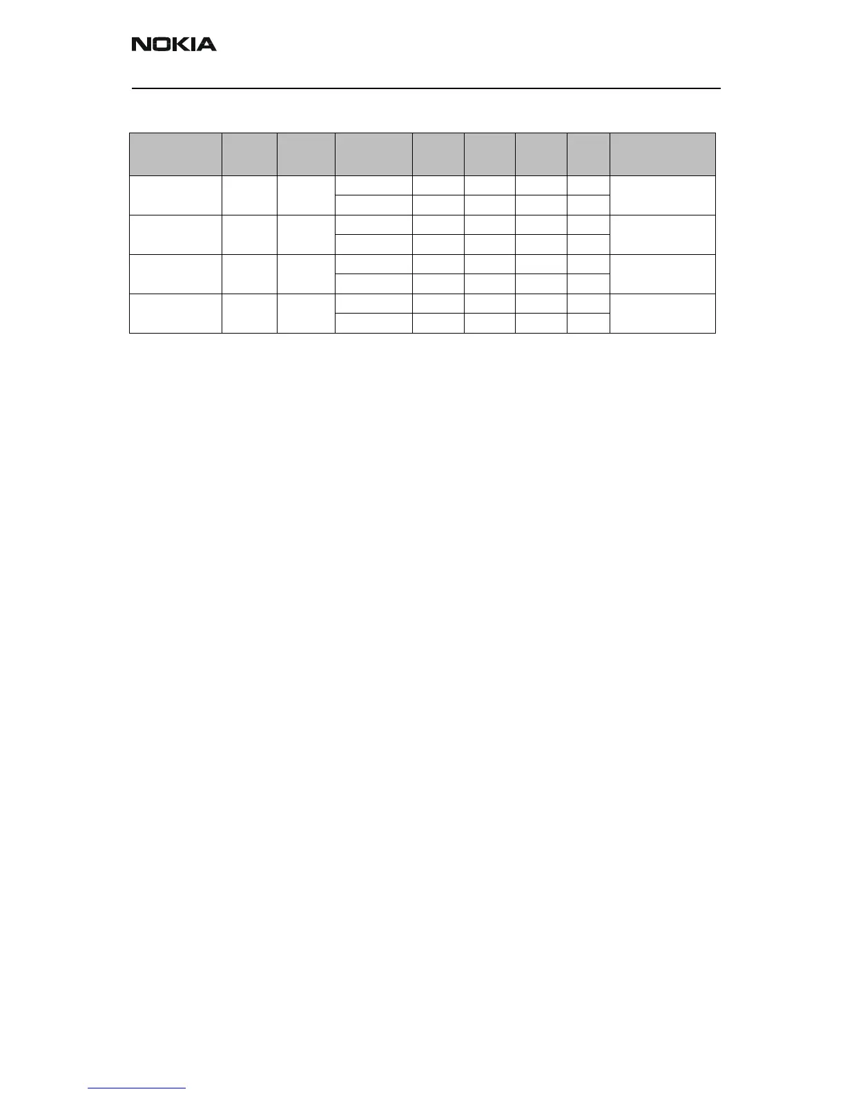
Table 2: BT – BB interface description
Signal name
MCM pin #
From To Para-
meter
Min. Typ. Max. Unit Notes
 Loading...