TFE-4/RV-1 Company Confidential
TF4 Technical Information Nokia Customer Care
Page 8b-42 Copyright © 2005 Nokia Corporation. Issue 2.0 Mar/2005
Company Confidential
RF power supplies are generated in the UEM and can be measured either in the Mjoelner
can or in the baseband can. Circles mark the measurement points in the pictures. Mea-
surement of VR7 inside Mjoelner can requires removal of RF shielding frame. Therefore,
VR7 shall be measured inside base band can.
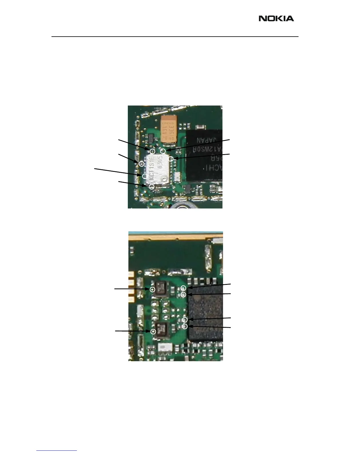
Measurement points in the receiver
Measurement points are shown in the pictures below.
Figure 25: RX measurement points at antenna switch module
Figure 26: RX measurement points at RX SAW filters and Mjoelner RF ASIC
There are no specific test points to measure RX I/Q signals. If necessary, RXIINN and
RXQINN signals can be measured by removing the solder resist on top of the vias. Shown
in the following picture.
CONT1 (VANTM)
CONT2 (VANTH)
ANT
Rx_GSM
Rx_DCS
CONT3 (VANTL)
IN (Z604)
IN (Z602)
INML (N601)
INPL (N601)
INMM (N601)
INPM (N601)
 Loading...