No group
No group
Operation
4-41
P/N 7105144G
2008 Nordson Corporation
VersaBlue_NW
Defining Groups (with ACM)
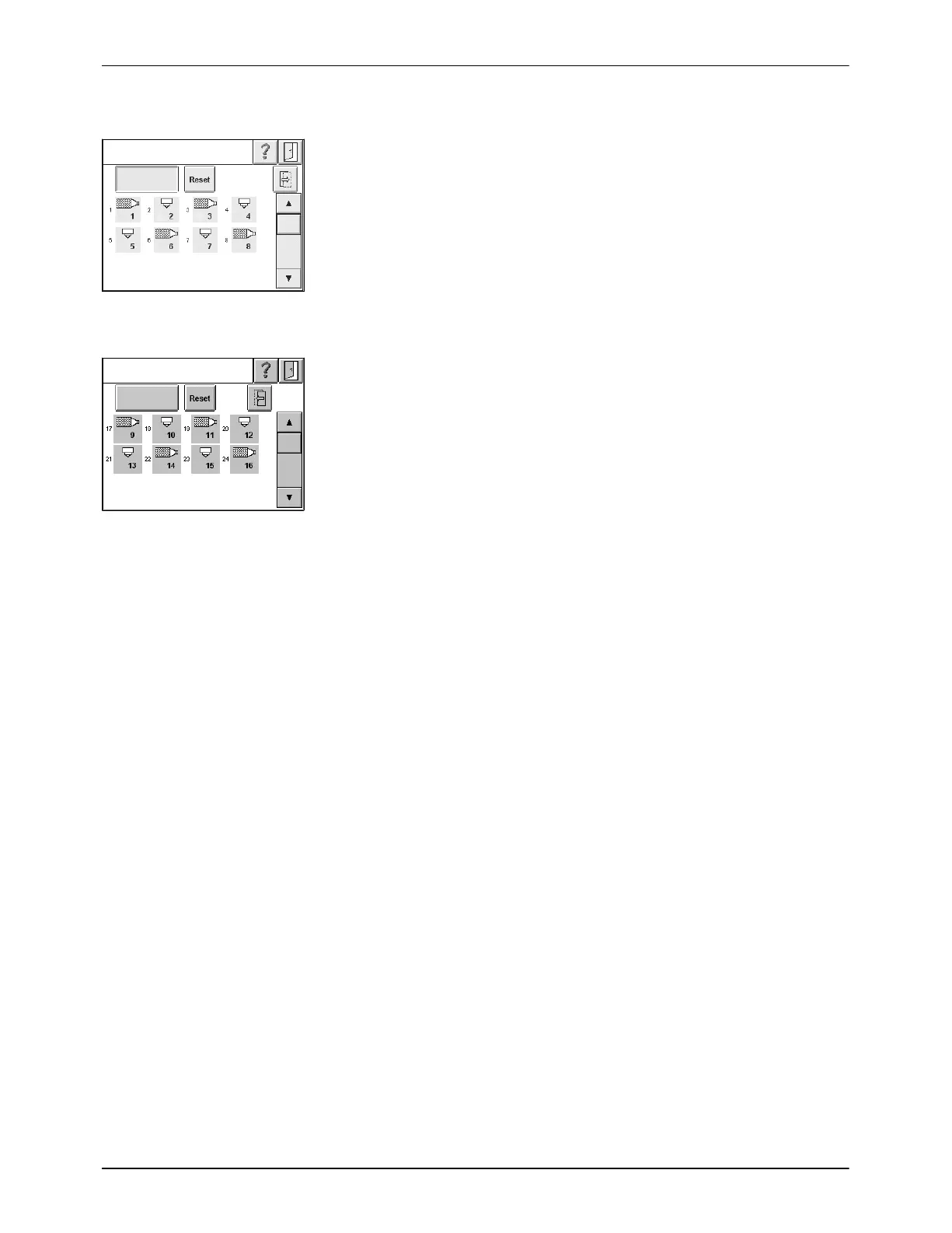
The first screen always indicates all of the temperature channels
allocated to the melter. There are no more than 16 channels (hose/gun
number 1 to 8); scroll if necessary.
The key To next screen appears if at least one of the two ACMs is available.
Touch the key to move to the next screen. All of the temperature channels in
the ACMs are shown here.
Fig. 4-41 V31
There are max. 36 channels, beginning with hose/gun number 9 to 26.
NOTE: Because there are several ways to set up an ACM, there is no fixed
assignment of channel to ACM. This information can be found in the wiring
diagram delivered with the respective ACM. If necessary, compare the P/N
on the ACM ID plate to the wiring diagram number.
Fig. 4-42 V31a
All temperature channels (except for grid and reservoir) can be combined to
application groups Group A to Group H. Channels not assigned to any
group belong to No group.
The channels of Group A, then Group B, etc. up to the channels without
group (No group) are displayed in the scan line of the starting screen.
Of the eight possible application groups, four can be switched via the
control panel as well as via the interface Standard I/O; the others can be
switched only via the control panel.
Refer to Standard I/O Group Inputs.

 Loading...