Ch5: Temperature sensor short-circuit
Alarm
history
Operation
4-42
P/N 7105144G
2008 Nordson Corporation
VersaBlue_NW
Melter (contd.)
Working with Application Groups (contd.)
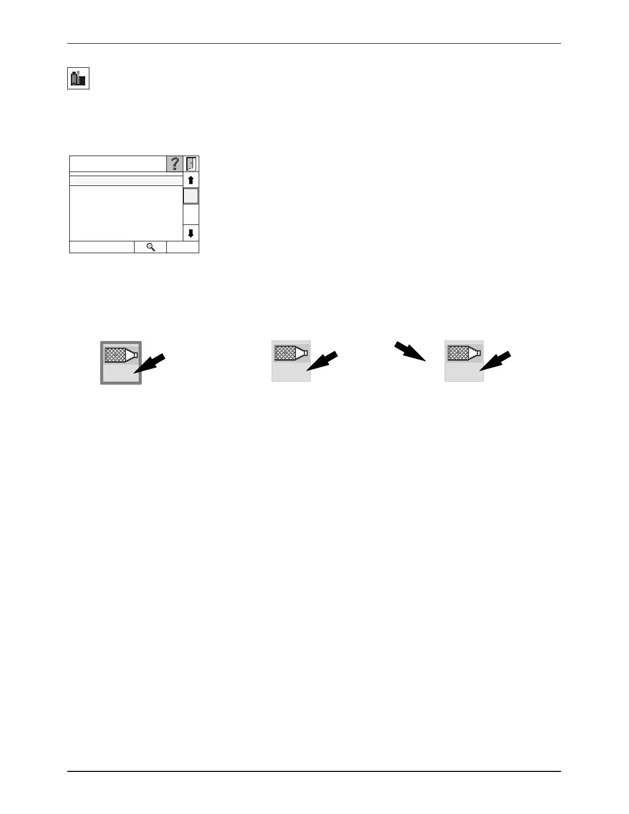
Displaying Channel Numbers on Control Panel
The numbers of the temperature channels shown on the control panel
(alarm lists and setpoints) are a factor of the settings made by the operator.
Ch5 (Channel 5): If a group contains at least one channel, the channel
number refers to the number below the channel symbol (arrow). To
determine the current channel numbers, refer to the screen Define Groups
on the control panel of the relevant melter.
Fig. 4-43 Alarm log
Channel Ch5 (when part of a
group)
Channel Ch5 (when not part of a
group), if at least one other
channel belongs to a group
Channel Ch5 (when not part of a
group), if no other channel
belongs to a group
B5
3
5
3
5
5
Transmitting Channel Groups via Field Bus
When the Channel number is transmitted via the field bus, the
melter-internal channels grid (low melt) and reservoir (high melt) occupy
numbers 1 and 2. This means that the external channels (guns, hoses, ...)
begin with number 3. The numbering of the wiring is the same as shown in
the wiring diagram and, unlike on the control panel, can not be changed.

 Loading...