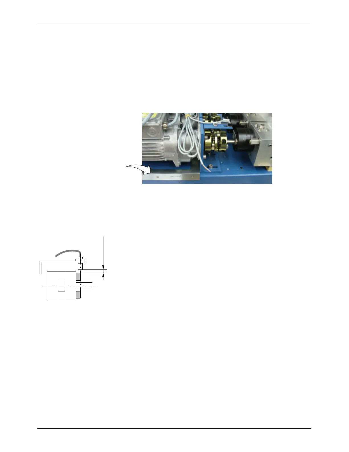
Coupling
max. 5 mm
Sensor
max. 0.2 in
Repair
7-15
P/N 7105144G
2008 Nordson Corporation
VersaBlue_NW
For more information on the coupling, refer to the manual VersaBlue,
section Repair, chapter Attaching Gear Pump, beginning with point 5.
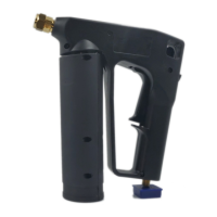
14. Slide the motor with the motor bracket in the slot until it lines up with the
first coupling element or protrudes no more than 1 to 2 mm (0.04 to
0.08 inch).
15. Align the motor bracket with the aid of an angle on the melter chassis;
refer to Figure 7-24.
For more information on the coupling, refer to the manual VersaBlue,
section Repair, chapter Replacing Motor.
Fig. 7-24
16. Tighten the motor bracket screws.
Torque (screws): 20 Nm / 177 lbin
17. Tighten coupling screws.
Torque (screws): 36 Nm / 320 lbin
18. Align sensor. Refer to Fig. 7-25.
NOTE: The dimensions indicated in the drawing (5 mm / 0.2 inch) must be
complied with.
19. Check if the drive and output shafts are aligned at low speed (5 min
−1
).
If not, align the motor anew.
20. Put the insulation blanket and protective panels back into place.
Fig. 7-25

 Loading...