Options
10-3
P/N 7105144G
2008 Nordson Corporation
VersaBlue_NW
Option in configuration
code
Box Also
available
as
accessory
Description
Safety valve with display 14 − O: The mechanical safety valve with Reed switch
replaces the installed mechanical safety valve.
There is no pressure control valve.
If filters or application nozzles are blocked, the
material pressure increases. The safety valve
opens at 85 bar, and the material flows back into
the tank.
The Reed switch on the safety valve generates an
electrical signal that can be emitted as a fault or a
warning.
Pressure display 15 − A: One pressure sensor per pump stream
(double-stream pumps are equipped with two
pressure sensors).
The melter outlet pressure is displayed and
monitored. Alarms for underpressure and
overpressure are displayed.
Level display 16 − L: Level sensor in tank for analog level display
Level display and filling valve 16 − B: Level control (Ni120)
C: Level control (Pt100)
Level sensor in tank for the analog level display
and the filling signals for a filling valve.
Automatic tank filling is performed e.g. by a bulk
melter connected to the filling valve with a hose.
Level display and filling valve
and overflow protection
16 − P: Level control (Ni120) with overflow protection
D: Level control (Pt100) with overflow protection
Level sensor in tank for the analog level display
and the filling signals for a filling valve.
Automatic tank filling is performed e.g. by a bulk
melter connected to the filling valve with a hose.
Additional level sensor in tank for separate overflow
protection
Level display (fixed
measuring points)
16 − F: The level sensor measures the presence of
material at five different fixed measuring points.
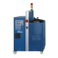
Light tower 17
W: Four colors. Indicates operating mode of melter.
Main switch 18 − 1: red-yellow, 4-pin
2: black, 3-pin
3: black, 4-pin
continued
 Loading...
