Point Program Program
NFS-3030 Programming Manual P/N 51345:C 11/4/03 43
modules with these categories of Type ID codes can participate in Local Mode: fire alarm,
supervisory, trouble. Refer to"Type Codes for Input Devices" on page 124 to determine which Type
ID codes fall into these categories. Default: OFF
3.4.3 Panel Circuit Module
There are three panel circuits on the FACP, and each circuit can accomodate up to four panel circuit
modules that have eight push-button switches apiece. The switches can be programmed as input or
output points, depending on the module type.
WARNING: When using alarm verification, do not mix fire alarm points with non-fire alarm
points on the same IZM-8RK/IZE-A Initiation Zone Module.
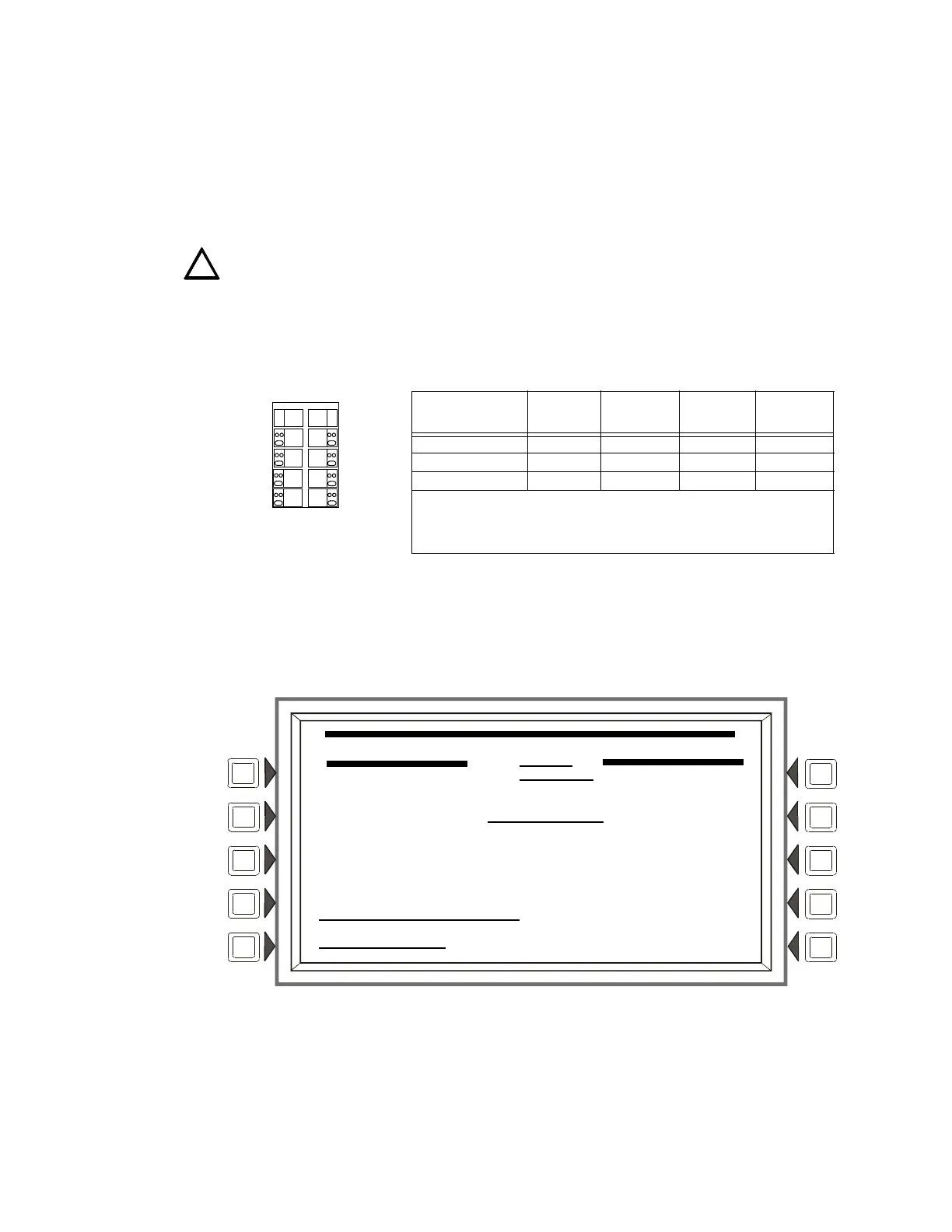
The point information is displayed onscreen in the format Pyy.z, where P means panel circuit
point, yy is the panel circuit module number (1 through 12), and z is the module push-button
number (1-8). Each panel circuit point is assigned an address by the panel depending on its
location. Refer to Figure 3.32 below for an illustration of how the panel assigns addresses.
Figure 3.32 Panel Circuit Point Addresses
Point Programming (1)
The Panel Circuit Point Programming screen will display if a panel circuit point address is entered
at the Point Programming Menu (see Figure 3.22 on page 34 ).
Figure 3.33 Panel Circuit Point Programming (1) Screen
Soft Keys
PANEL MODULE TYPE: Press the soft key to toggle between MONITOR, CONTROL-CRM,
CONTROL-ICM. Select MONITOR for IZM-8RK/IZE-A modules, CONTROL-CRM for
CRM-4RK/CRE4 modules, and CONTROL-ICM for ICM-4RK/ICE-4 modules.
TYPE CODE LABEL: Press this soft key to scroll through the point Type Code choices: stop at
!
.
CPU-3030 Panel
Circuit Connection
1st position*
module
addresses
2nd position
module
addresses
3rd position
module
addresses
4th position
module
addresses
Panel Circuit #1 (J10) P1.1 - P1.8 P2.1 - P2.8 P3.1 - P3.8 P4.1 - P4.8
Panel Circuit #2 (J11) P5.1 - P5.8 P6.1 - P6.8 P7.1 - P7.8 P8.1 - P8.8
Panel Circuit #3 (J12) P9.1 - P9.8 P10.1 - P10.8 P11.1 - P11.8 P12.1 - P12.8
* The first position is the position closest to the CPU-3030 connection, the
fourth position is the furthest from this connection. These address assignments are
fixed; if a panel module is not installed in position 3 of panel circuit #1, the fourth
position module still has an address of P4.yy.
Pyy.1
Pyy.2
Pyy.3
Pyy.4
Pyy.5
Pyy.8
Pyy.6
Pyy.7
Panel Circuit Module
PANEL CKT POINT PROGRAMMING
P11.2
PANEL MODULE TYPE: MONITOR
TYPE CODE LABEL:HEAT DETECT
MORE
POINT LABEL: ACCEPT
EXTENDED LABEL:
BACK
www.PDF-Zoo.com