8.4 ELECTRONIC CONTROL
UNIT
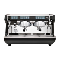
1 To remove the electronic control unit, dis-
connect all connecting wires and four lock-
ing screws on the frame.
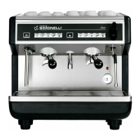
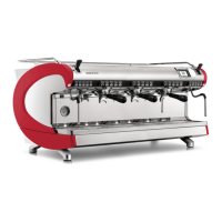
2 At the top of the unit are:
(A) Fuse [6.3 A]
(B) Input power transformer and motor
output
(C) Motor encoder
(D) Autosteam probe (only if the autosteam
option is present)
(E) Sensor group
(F) Water tank level
(G) Boiler tank level
(H) Trim for autosteam temperature probe
calibration
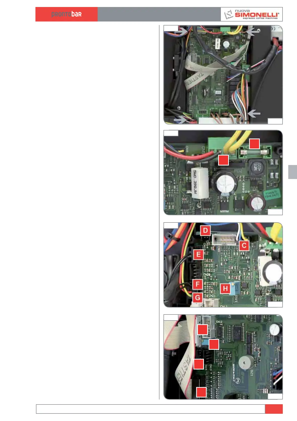
3 On the left side:
(A) Display connection
(B) Keyboard connection
(C) USB connection
(D) Trim for display contrast
Edition 02 to 02/2014
8.7
SERVICE MANUAL
Fig. 197
01:10
Fig. 199
01:21
Fig. 200
01:36
Fig. 198
01:12