103
Communications Functions Section 1-9
Communications
Procedure
If the settings for the master and the slave are made correctly, then the one-
to-one link will be automatically started up simply by turning on the power
supply to both the CQM1s and operation will be independent of the CQM1
operating modes.
Link Errors If a slave does not received a response from the master within one second,
the 1:1 Link Error Flag (AR 0802) and the Communications Error Flag (AR
0804) will be turned ON.
Application Example This example shows a program for verifying the conditions for executing a
one-to-one link using the RS-232C ports. Before executing the program, set
the following PC Setup parameters.
Master: DM 6645: 3200 (one-to-one link master; Area used: LR 00 to LR 15)
Slave: DM 6645: 2000 (one-to-one link slave)
The defaults are assumed for all other PC Setup parameters. The words used
for the one-to-one link are as shown below.
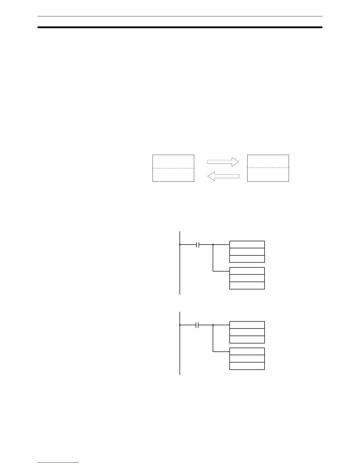
When the program is executed at both the master and the slave, the status of
IR 001 of each Unit will be reflected in IR 100 of the other Unit. Likewise, the
status of the other Unit’s IR 001 will be reflected in IR 100 of each Unit. IR 001
is an input word and IR 100 is an output word
In the Master
In the Slave
LR00
LR07
LR08
LR15
LR00
LR07
LR08
LR15
Master
Area for writing
Area for reading
Slave
Area for writing
Area for reading
25313 (Always ON)
MOV(21)
001
LR00
MOV(21)
LR08
100
MOV(21)
001
LR08
MOV(21)
LR00
100
25313 (Always ON)

 Loading...


