164
Basic Ladder Diagrams Section 4-3
instruction at the right, the logical AND of the execution conditions resulting
from these two blocks would have to be taken. AND LOAD does this. The
mnemonic code for the ladder diagram is shown below. The AND LOAD
instruction requires no operands of its own, because it operates on previously
determined execution conditions. Here too, dashes are used to indicate that
no operands needs designated or input.
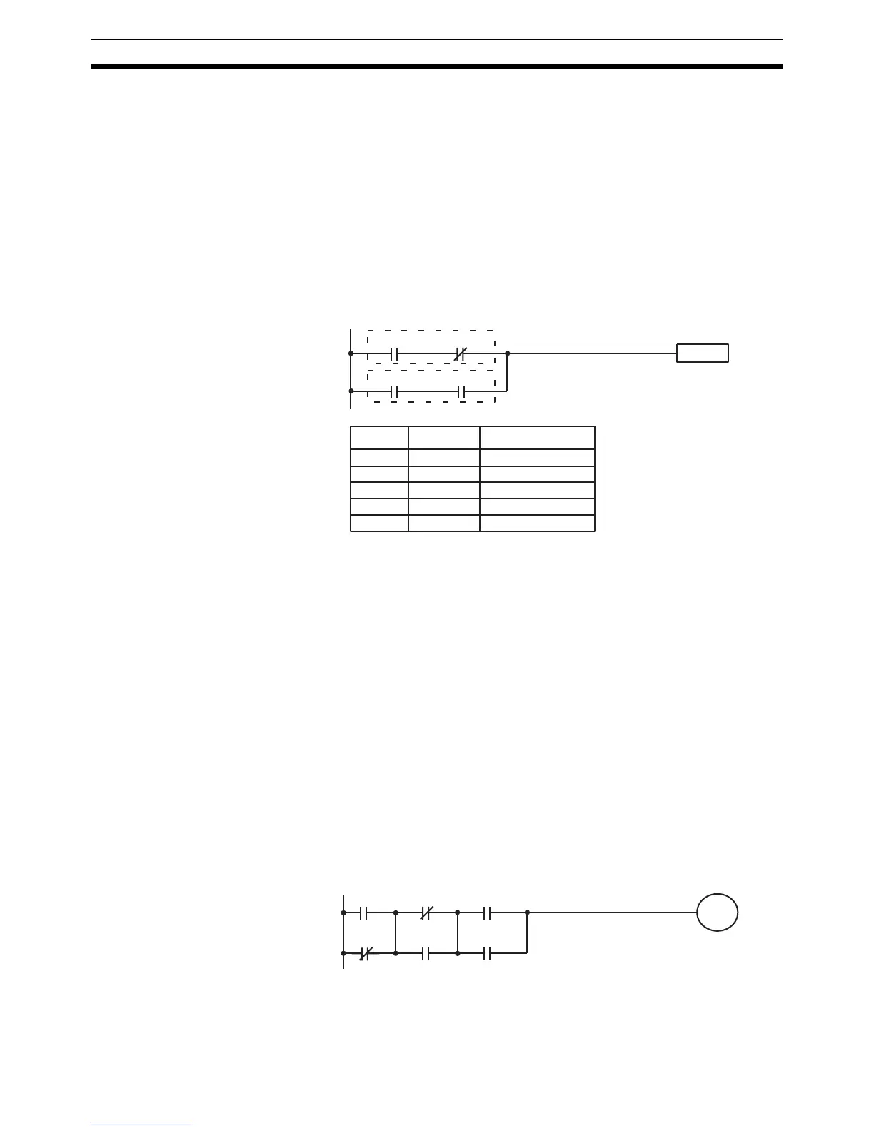
OR LOAD The following diagram requires an OR LOAD instruction between the top logic
block and the bottom logic block. An ON execution condition would be pro-
duced for the instruction at the right either when IR 00000 is ON and IR 00001
is OFF or when IR 00002 and IR 00003 are both ON. The operation of and
mnemonic code for the OR LOAD instruction is exactly the same as those for
a AND LOAD instruction except that the current execution condition is ORed
with the last unused execution condition.
Naturally, some diagrams will require both AND LOAD and OR LOAD instruc-
tions.
Logic Block Instructions
in Series
To code diagrams with logic block instructions in series, the diagram must be
divided into logic blocks. Each block is coded using a LOAD instruction to
code the first condition, and then AND LOAD or OR LOAD is used to logically
combine the blocks. With both AND LOAD and OR LOAD there are two ways
to achieve this. One is to code the logic block instruction after the first two
blocks and then after each additional block. The other is to code all of the
blocks to be combined, starting each block with LOAD or LOAD NOT, and
then to code the logic block instructions which combine them. In this case, the
instructions for the last pair of blocks should be combined first, and then each
preceding block should be combined, working progressively back to the first
block. Although either of these methods will produce exactly the same result,
the second method, that of coding all logic block instructions together, can be
used only if eight or fewer blocks are being combined, i.e., if seven or fewer
logic block instructions are required.
The following diagram requires AND LOAD to be converted to mnemonic
code because three pairs of parallel conditions lie in series. The two means of
coding the programs are also shown.
Instruction
00000 00001
00002 00003
Address Instruction Operands
00000 LD 00000
00001 AND NOT 00001
00002 LD 00002
00003 AND 00003
00004 OR LD ---
00000 00002 00004
00001 00003 00005
10000

 Loading...


