EasyManuals Logo

Omron CPM1 Programming Manual

Omron CPM1
541 pages
To Next Page IconTo Next Page
To Previous Page IconTo Previous Page
Page #191 background imageLoading...
Page #191 background image
170
Basic Ladder Diagrams Section 4-3
Again, this diagram can be redrawn as follows to simplify program structure
and coding and to save memory space.
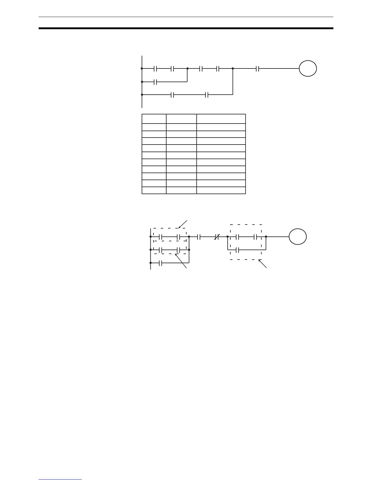
The next and final example may at first appear very complicated but can be
coded using only two logic block instructions. The diagram appears as follows:
00006 00007
LR 0000
00005
00001 00002
00003 00004 00000
Address Instruction Operands
00000 LD 00006
00001 AND 00007
00002 OR 00005
00003 AND 00003
00004 AND 00004
00005 LD 00001
00006 AND 00002
00007 OR LD --
00008 AND 00000
00009 OUT LR 0000
00000 00001
10000
00002 00003
01000 01001
00004 00005
10000
00006
Block cBlock b
Block a

Table of Contents

Other manuals for Omron CPM1

Questions and Answers:

Question and Answer IconNeed help?

Do you have a question about the Omron CPM1 and is the answer not in the manual?

Omron CPM1 Specifications

General IconGeneral
ModelCPM1
ManufacturerOmron
Instruction SetBasic and advanced instructions
Power Supply100 to 240 VAC or 24 VDC
CommunicationRS-232C
I/O Points10, 20, 30, or 40 points depending on the model
TimersYes, multiple timers available
CountersYes, multiple counters available
Input Voltage24V DC
Output TypeRelay or transistor
Number of I/O Points10, 20, 30, 40
Communication PortsRS-232C (optional)
Operating Temperature0°C to 55°C
Storage Temperature-20°C
Humidity10% to 90% (non-condensing)
DimensionsVaries depending on the model
WeightVaries depending on the model
Program Memory2048 steps (2K steps)

Related product manuals