EasyManuals Logo

Omron CPM1 Programming Manual

Omron CPM1
541 pages
To Next Page IconTo Next Page
To Previous Page IconTo Previous Page
Page #192 background imageLoading...
Page #192 background image
171
Basic Ladder Diagrams Section 4-3
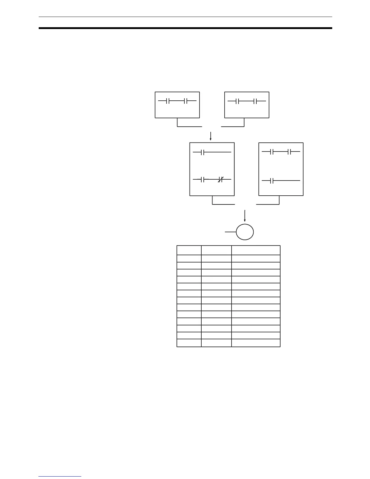
The first logic block instruction is used to combine the execution conditions
resulting from blocks a and b, and the second one is to combine the execution
condition of block c with the execution condition resulting from the normally
closed condition assigned IR 00003. The rest of the diagram can be coded
with OR, AND, and AND NOT instructions. The logical flow for this and the
resulting code are shown below.
00004 00005
00002 00003
00000 00001
01000 01001
10000
10000
00006
Block c
Block bBlock a
OR LD
LD 00000
AND 00001
OR 10000
AND 00002
AND NOT 00003
LD 01000
AND 01001
OR 00006
LD 00004
AND 00005
AND LD
Address Instruction Operands
00000 LD 00000
00001 AND 00001
00002 LD 01000
00003 AND 01001
00004 OR LD --
00005 OR 10000
00006 AND 00002
00007 AND NOT 00003
00008 LD 00004
00009 AND 00005
00010 OR 00006
00011 AND LD --
00012 OUT 10000

Table of Contents

Other manuals for Omron CPM1

Questions and Answers:

Question and Answer IconNeed help?

Do you have a question about the Omron CPM1 and is the answer not in the manual?

Omron CPM1 Specifications

General IconGeneral
ModelCPM1
ManufacturerOmron
Instruction SetBasic and advanced instructions
Power Supply100 to 240 VAC or 24 VDC
CommunicationRS-232C
I/O Points10, 20, 30, or 40 points depending on the model
TimersYes, multiple timers available
CountersYes, multiple counters available
Input Voltage24V DC
Output TypeRelay or transistor
Number of I/O Points10, 20, 30, 40
Communication PortsRS-232C (optional)
Operating Temperature0°C to 55°C
Storage Temperature-20°C
Humidity10% to 90% (non-condensing)
DimensionsVaries depending on the model
WeightVaries depending on the model
Program Memory2048 steps (2K steps)

Related product manuals