169
Basic Ladder Diagrams Section 4-3
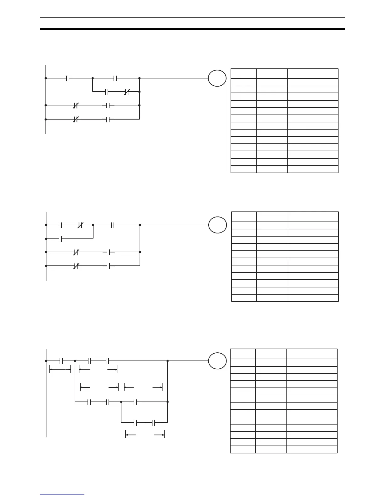
The following diagram requires an OR LOAD followed by an AND LOAD to
code the top of the three blocks, and then two more OR LOADs to complete
the mnemonic code.
Although the program will execute as written, this diagram could be drawn as
shown below to eliminate the need for the first OR LOAD and the AND LOAD,
simplifying the program and saving memory space.
The following diagram requires five blocks, which here are coded in order
before using OR LOAD and AND LOAD to combine them starting from the
last two blocks and working backward. The OR LOAD at program address
00008 combines blocks blocks d and e, the following AND LOAD combines
the resulting execution condition with that of block c, etc.
00002 00003
LR 0000
00000
00001
00004 00005
00006 00007
Address Instruction Operands
00000 LD 00000
00001 LD 00001
00002 LD 00002
00003 AND NOT 00003
00004 OR LD --
00005 AND LD --
00006 LD NOT 00004
00007 AND 00005
00008 OR LD --
00009 LD NOT 00006
00010 AND 00007
00011 OR LD --
00012 OUT LR 0000
00002 00003
LR 0000
00001
00000
00004 00005
00006 00007
Address Instruction Operands
00000 LD 00002
00001 AND NOT 00003
00002 OR 00001
00003 AND 00000
00004 LD NOT 00004
00005 AND 00005
00006 OR LD --
00007 LD NOT 00006
00008 AND 00007
00009 OR LD --
00010 OUT LR 0000
LR 0000
00000
00003
00004
00006 00007
00001 00002
00005
Block e
Block d
Block c
Block b
Block a
Address Instruction Operands
Blocks d and e
Block c with result of above
Block b with result of above
Block a with result of above
00000 LD 00000
00001 LD 00001
00002 AND 00002
00003 LD 00003
00004 AND 00004
00005 LD 00005
00006 LD 00006
00007 AND 00007
00008 OR LD --
00009 AND LD --
00010 OR LD --
00011 AND LD --
00012 OUT LR 0000

 Loading...


