361
Communications Procedure Section 6-1
Frame Transmission and Reception
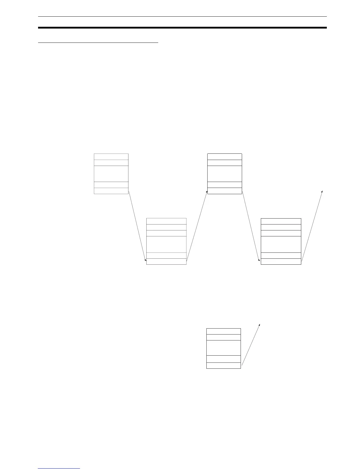
Commands and responses are exchanged in the order shown in the illustra-
tion below. The block of data transferred in a single transmission is called a
“frame.” A single frame is configured of a maximum of 131 characters of data.
The right to send a frame is called the “transmission right.” The Unit that has
the transmission right is the one that can send a frame at any given time. The
transmission right is traded back and forth between the host computer and the
PC each time a frame is transmitted. The transmission right is passed from
the transmitting Unit to the receiving Unit when either a terminator (the code
that marks the end of a command or response) or a delimiter (the code that
sets frames apart) is received.
Commands from Host In host link communications, the host computer ordinarily has the transmis-
sion right first and initiates the communications. The PC then automatically
sends a response.
Commands from PC
(CQM1 Only)
With CQM1 PCs, it is also possible in host link communications for the PC to
send commands to the host computer. In this case it is the PC that has the
transmission right and initiates the communications.
When commands are issued to the host computer, the data is transmitted in
one direction from the PC to the host computer. If a response to a command is
required use a host link communications command to write the response from
the host computer to the PC.
Terminator
FCS
Tex t
Tex t
End code
Header code
Unit no.
Unit no.
Header code
FCS
Terminator
Frame (response)
Frame (command)
Next frame transmission
enabled (i.e., transmission
right transferred)
Tex t
Unit no.
Header code
FCS
Terminator
Frame (command)
Terminator
FCS
Tex t
End code
Header code
Unit no.
Frame
(response)
Host
computer
PC
No response
Tex t
Unit no.
Header code
FCS
Terminator
Host
computer
PC
 Loading...


