EasyManuals Logo

Omron CPM1 Programming Manual

Omron CPM1
541 pages
To Next Page IconTo Next Page
To Previous Page IconTo Previous Page
Page #467 background imageLoading...
Page #467 background image
446
Troubleshooting Flowcharts Section 8-8
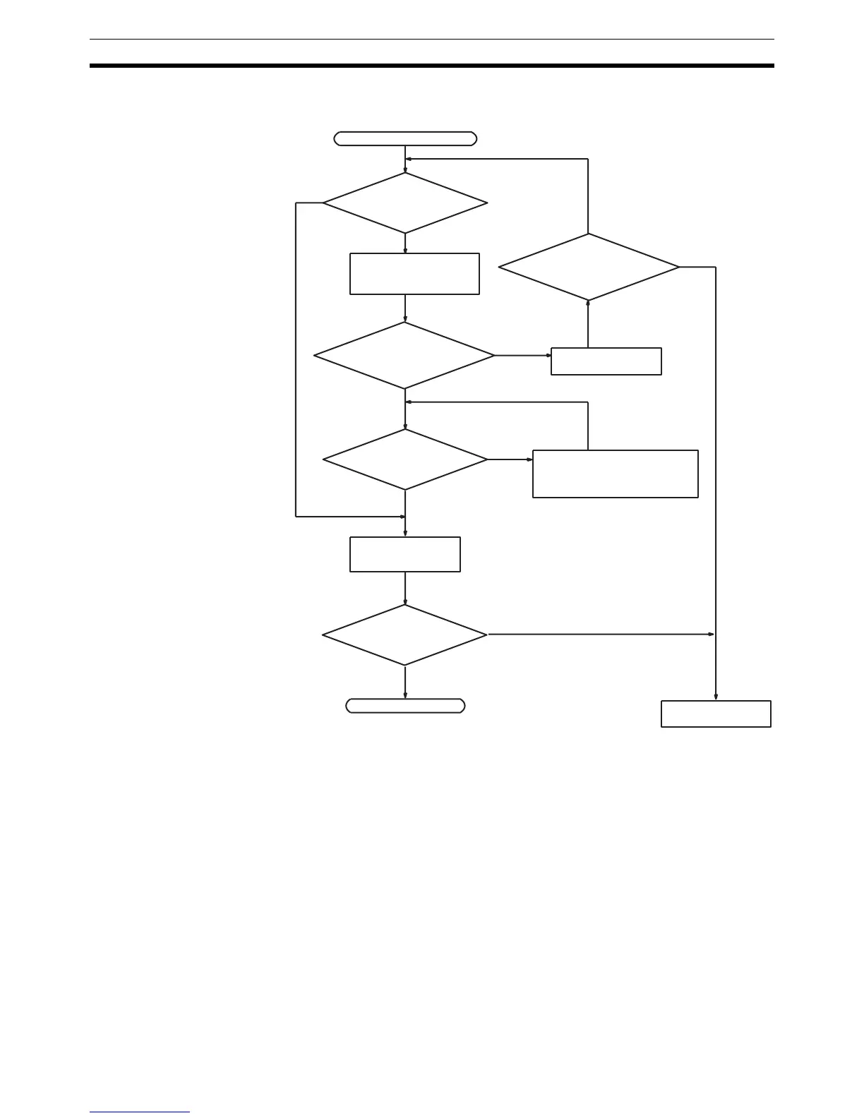
Fatal Error Check The following flowchart can be used to troubleshoot fatal errors that occur
while the Power indicator is lit.
Identify the error, eliminate
its cause, and clear the er-
ror.
Is the ERR/ALM
indicator lit?
Determine the cause
of the error with a
Peripheral Device.
End
RUN indicator not lit.
Replace the CPU
Unit.
Is PC mode displayed
on Peripheral Device?
Correct the power
supply.
Switch to RUN or
MONITOR mode.
No
Ye s
Is a fatal error
displayed?
Is PC mode displayed
on Peripheral Device?
No
Ye s
Ye s
No
Is the RUN indi-
cator lit?
No
Ye s
Ye s
No

Table of Contents

Other manuals for Omron CPM1

Questions and Answers:

Question and Answer IconNeed help?

Do you have a question about the Omron CPM1 and is the answer not in the manual?

Omron CPM1 Specifications

General IconGeneral
ModelCPM1
ManufacturerOmron
Instruction SetBasic and advanced instructions
Power Supply100 to 240 VAC or 24 VDC
CommunicationRS-232C
I/O Points10, 20, 30, or 40 points depending on the model
TimersYes, multiple timers available
CountersYes, multiple counters available
Input Voltage24V DC
Output TypeRelay or transistor
Number of I/O Points10, 20, 30, 40
Communication PortsRS-232C (optional)
Operating Temperature0°C to 55°C
Storage Temperature-20°C
Humidity10% to 90% (non-condensing)
DimensionsVaries depending on the model
WeightVaries depending on the model
Program Memory2048 steps (2K steps)

Related product manuals