468
Memory Areas Appendix C
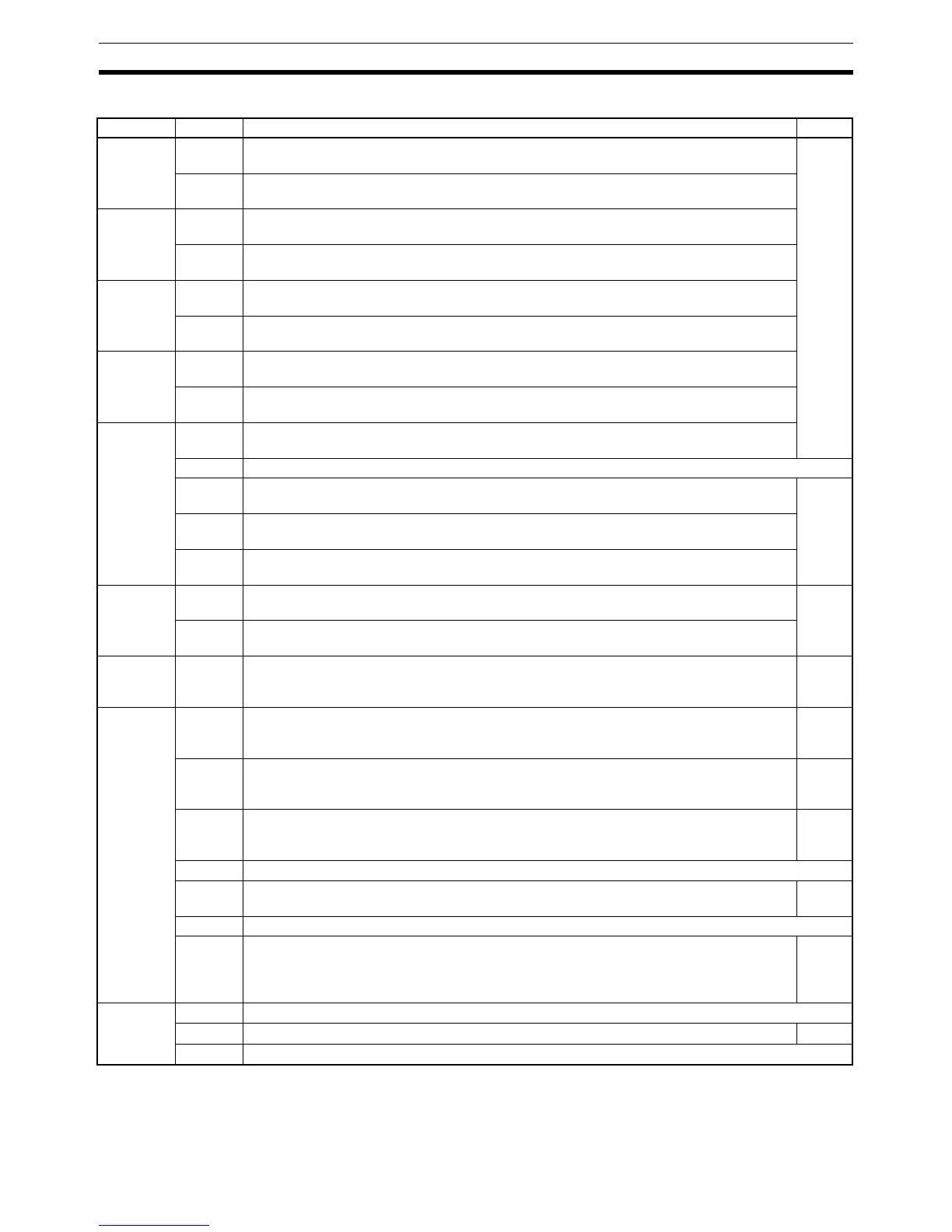
Word Bit(s) Function Page
AR 17 00 to 07 “Minutes” portion of the present time, in 2 digits BCD (Valid only when a Memory Cas-
sette with the clock function is installed.)
136
08 to 15 “Hour” portion of the present time, in 2 digits BCD (Valid only when a Memory Cassette
with the clock function is installed.)
AR 18 00 to 07 “Seconds” portion of the present time, in 2 digits BCD (Valid only when a Memory Cas-
sette with the clock function is installed.)
08 to 15 “Minutes” portion of the present time, in 2 digits BCD (Valid only when a Memory Cas-
sette with the clock function is installed.)
AR 19 00 to 07 “Hour” portion of the present time, in 2 digits BCD (Valid only when a Memory Cassette
with the clock function is installed.)
08 to 15 “Date” portion of the present time, in 2 digits BCD (Valid only when a Memory Cassette
with the clock function is installed.)
AR 20 00 to 07 “Month” portion of the present time, in 2 digits BCD (Valid only when a Memory Cassette
with the clock function is installed.)
08 to 15 “Year” portion of the present time, in 2 digits BCD (Valid only when a Memory Cassette
with the clock function is installed.)
AR 21 00 to 07 “Day of week” portion of the present time, in 2 digits BCD [00: Sunday to 06: Saturday]
(Valid only when a Memory Cassette with the clock function is installed.)
08 to 12 Not used.
13 30-second Adjustment Bit
Valid only when a Memory Cassette with the clock function is installed.
136
14 Clock Stop Bit
Valid only when a Memory Cassette with the clock function is installed.
15 Clock Set Bit
Valid only when a Memory Cassette with the clock function is installed.
AR 22 00 to 07 Input Words
Number of words for input bits (2 digits BCD)
139
08 to 15 Output Words
Number of words for output bits (2 digits BCD)
AR 23 00 to 15 Power-off Counter (4 digits BCD)
This is the count of the number of times that the power has been turned off. To clear the
count, write “0000” from a peripheral device.
---
AR 24 00 Power-up PC Setup Error Flag
Turns ON when there is an error in DM 6600 to DM 6614 (the part of the PC Setup area
that is read at power-up).
3
01 Start-up PC Setup Error Flag
Turns ON when there is an error in DM 6615 to DM 6644 (the part of the PC Setup area
that is read at the beginning of operation).
439
02 RUN PC Setup Error Flag
Turns ON when there is an error in DM 6645 to DM 6655 (the part of the PC Setup area
that is always read).
3
03, 04 Not used.
05 Long Cycle Time Flag
Turns ON if the actual cycle time is longer than the cycle time set in DM 6619.
---
06, 07 Not used.
08 to 15 Code (2 digits hexadecimal) showing the word number of a detected I/O bus error
00 to 07:Correspond to input words 000 to 007.
80 to 87:Correspond to output words 100 to 107.
FF: End cover cannot be confirmed.
---
AR 25 00 to 07 Not used.
08 FPD(––) Teaching Bit
330
09 to 15 Not used.
 Loading...


