41
CQM1 Interrupt Functions Section 1-5
Input Interrupt Mode Use the following instructions to program input interrupts using the Input Inter-
rupt Mode.
Masking of Interrupts
With the INT(89) instruction, set or clear input interrupt masks as required.
At the beginning of operation, all of the input interrupts are masked.
Clearing Masked Interrupts
If the bit corresponding to an input interrupt turns ON while masked, that input
interrupt will be saved in memory and will be executed as soon as the mask is
cleared. In order for that input interrupt not to be executed when the mask is
cleared, the interrupt must be cleared from memory.
Only one interrupt signal will be saved in memory for each interrupt number.
With the INT(89) instruction, clear the input interrupt from memory.
Reading Mask Status
With the INT(89) instruction, read the input interrupt mask status.
Counter Mode Use the following steps to program input interrupts using the Input Interrupt
Mode.
Note The SR words used in the Counter Mode (SR 244 to SR 251) all contain
binary (hexadecimal) data (not BCD).
1,2,3... 1. Write the set values for counter operation to SR words correspond to inter-
rupts 0 to 3. The set values are written between 0000 and FFFF (0 to
65,535). A value of 0000 will disable the count operation until a new value
is set and step 2, below, is repeated.
Note These SR bits are cleared at the beginning of operation, and must be
written from the program.
That maximum input signal that can be counted is 1 kHz.
If the Counter Mode is not used, these SR bits can be used as work bits.
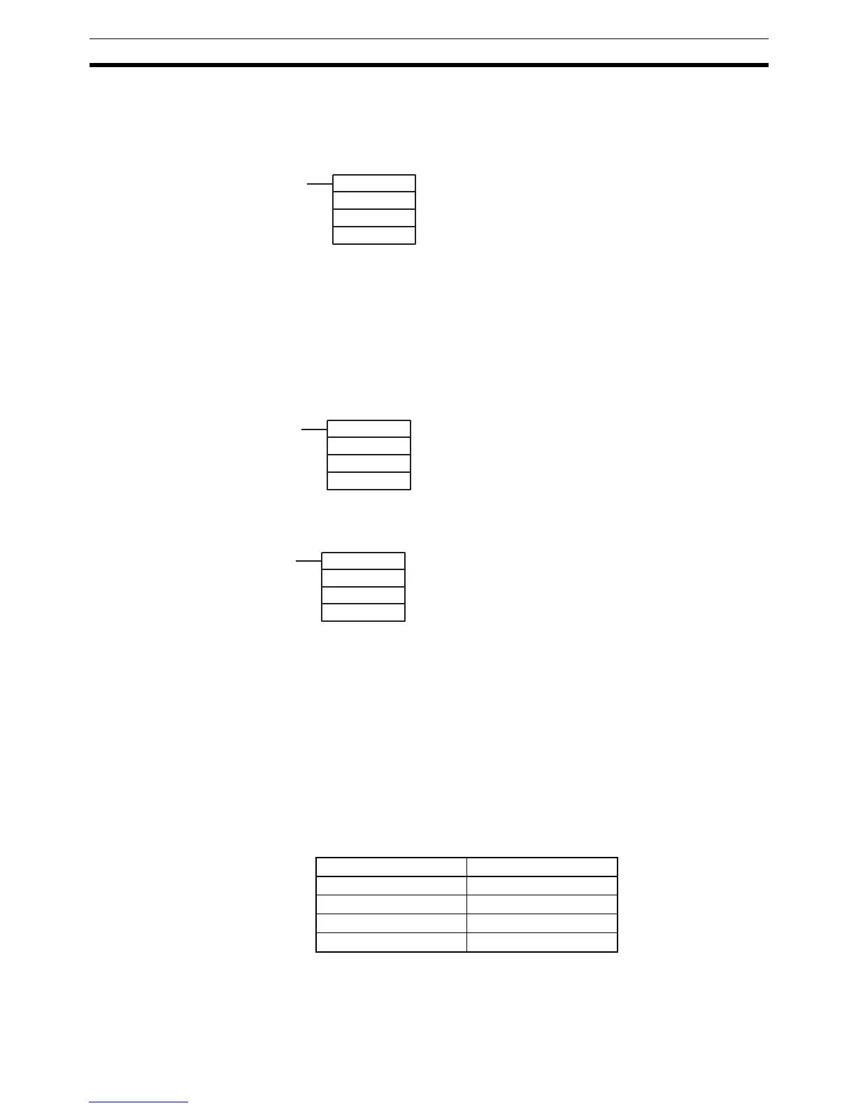
(@)INT(89)
000
000
D
Make the settings with the D bits 0 to 3, which correspond to
input interrupts 0 to 3.
0: Mask cleared. (Input interrupt permitted.)
1: Mask set. (Input interrupt not permitted.)
(@)INT(89)
001
000
D
If D bits 0 to 3, which correspond to input interrupts 0 to 3, are
set to "1," then the input interrupts will be cleared from memory.
0: Input interrupt retained.
1: Input interrupt cleared.
(@)INT(89)
002
000
D
The status of the rightmost digit of the data stored in word D (bits
0 to 3) show the mask status.
0: Mask cleared. (Input interrupt permitted.)
1: Mask set. (Input interrupt not permitted.)
Interrupt Word
Input interrupt 0 SR 244
Input interrupt 1 SR 245
Input interrupt 2 SR 246
Input interrupt 3 SR 247

 Loading...


