52
CQM1 Interrupt Functions Section 1-5
Using the PRV(62) Instruction
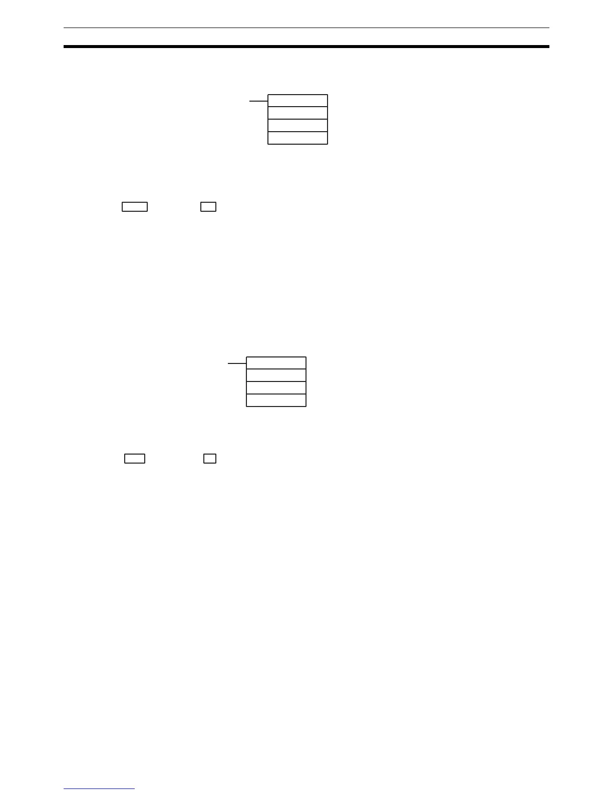
Read the PV of high-speed counter 0 by using the PRV(62) instruction.
The PV of high-speed counter 0 is stored as shown below. The leftmost bit will
be F for negative values.
The PV is read when the PRV(62) instruction is actually executed.
Changing the PV
There are two ways to change the PV of high-speed counter 0. The first way is
to reset it by using the reset methods. (In this case the PV is reset to 0.) The
second way is to use the INI(61) instruction.
The method using the INI(61) instruction is explained here. For an explanation
of the reset method, refer to the beginning of this description of high-speed
counter 0.
Change the timer PV by using the INI(61) instruction as shown below.
To specify a negative number, set F in the leftmost digit.
Operation Example This example shows a program for using high-speed counter 0 in the Incre-
menting Mode, making comparisons by means of the target matching method,
and changing the frequency of pulse outputs according to the counter’s PV.
Before executing the program, set the PC Setup as follows:
DM 6642: 0114 (High-speed counter 0 used with software reset and Incre-
menting Mode). For all other PC Setup, use the default settings. (Inputs are
not refreshed at the time of interrupt processing, and pulse outputs are exe-
cuted for IR 100.)
(@)PRV(62)
000
000
P1
P1: Leading word of PV
Leftmost 4 digits Rightmost 4 digits Up/Down Mode Incrementing Mode
P1+1 P1 F0032767 to 00032767
(–32767)
00000000 to 00065535
Leftmost 4 digits Rightmost 4 digits Up/Down Mode Incrementing Mode
D+1 D F0032767 to 00032767 00000000 to 00065535
(@)INI(61)
000
002
D
D: Leading word for storing PV change data