59
CQM1 Interrupt Functions Section 1-5
Note These words are refreshed only once every cycle, so there may be a differ-
ence from the actual PV.
Using the PRV(62) Instruction
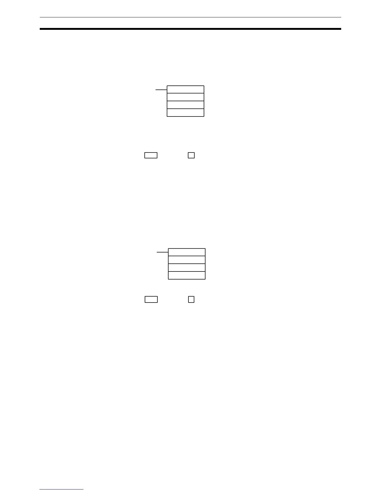
Read the PV of high-speed counter 0 by using the PRV(62) instruction. Spec-
ify high-speed counter 1 or 2 in P (P=001 or 002).
The PV of the specified high-speed counter is stored as shown below. In lin-
ear mode, the leftmost bit will be F for negative values.
The PV is read when the PRV(62) instruction is actually executed.
Changing the PV
There are two ways to change the PV of high-speed counters 1 and 2. The
first way is to reset it by using the reset methods. (In this case the PV is reset
to 0.) The second way is to use the INI(61) instruction.
The method using the INI(61) instruction is explained here. For an explanation
of the reset method, refer to the beginning of this description of high-speed
counters 1 and 2.
Change the timer PV by using the INI(61) instruction as shown below.
To specify a negative number in linear mode, set F in the leftmost digit.
Note Do not use INI(61) to repeatedly change the PV and start comparison for tar-
get value comparison while pulses are being input. If the comparison opera-
tion is started immediately after forcing the PV to change, the interrupts may
not work properly. The target value will return to the first target value following
completion of the interrupt for it, enabling repeating operation by only chang-
ing the PV.
High-speed Counter
Status
The status of high-speed counters 1 and 2 can be determined either by read-
ing the status of the relevant flags in the AR area or executing PRV(62).
(@)PRV(62)
P
000
P1
P: Port (001: port 1; 002: port 2)
P1: Leading word of PV
Leftmost 4 digits Rightmost 4 digits Linear Mode Ring Mode
D+1 D F8388607 to 08388607
(–8,388,607 to 8,388,607)
00000000 to 00064999
(@)INI(61)
P
002
D
P: Port (001: port 1; 002: port 2)
D: Leading word for storing PV change dat
 Loading...


