60
CQM1 Interrupt Functions Section 1-5
The following table shows the relevant AR area flags and their functions.
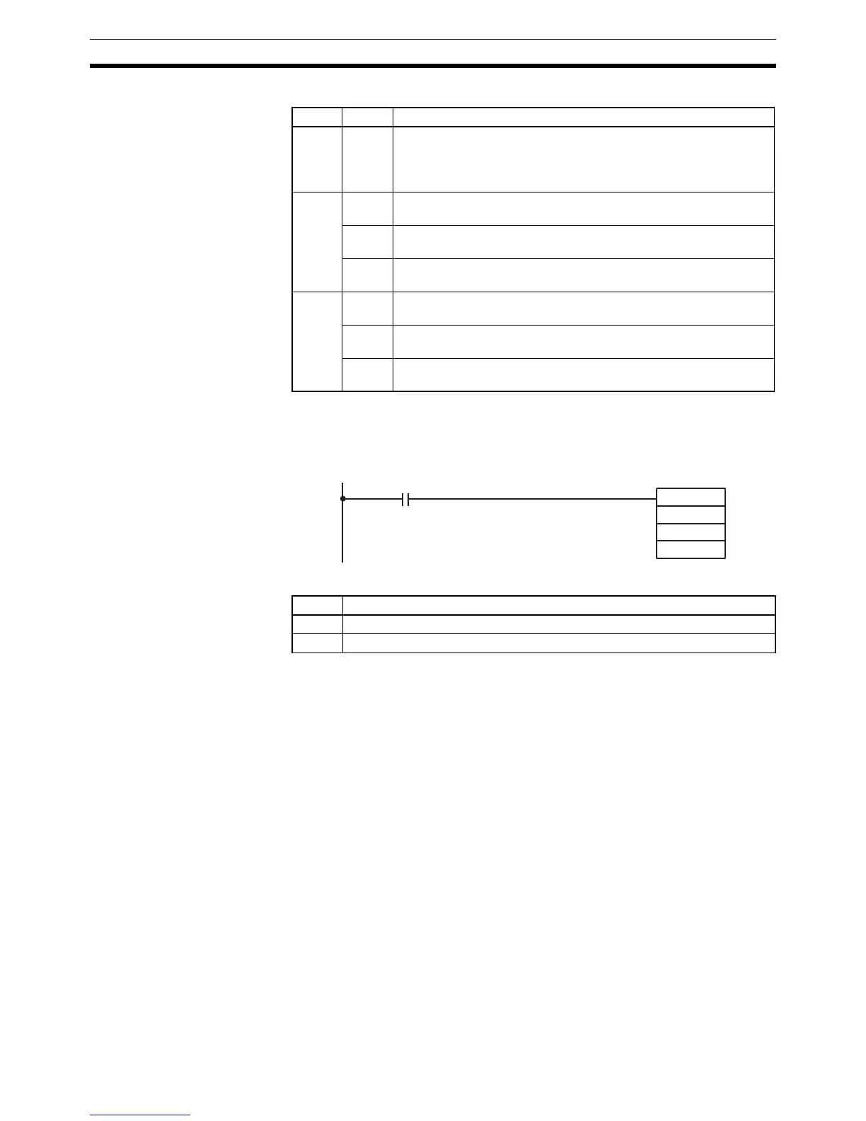
The status of high-speed counters 1 and 2 can also be determined by execut-
ing PRV(62). Specify high-speed counter 1 or 2 (P=001 to 002) and the desti-
nation word D. The status information will be written to bits 00 and 01 of D.
Bits 02 to 15 will be set to 0.
Bits 00 and 01 of D contain the specified high-speed counter’s status.
Operation Example This example shows a program that outputs standard pulses from port 1 while
counting those pulses with high-speed counter 1. The high-speed counter
operates in Up/Down Mode, with the pulse output’s CW pulses incrementing
the counter (B-phase input) and the CCW pulses decrementing the counter
(A-phase input). Before executing the program, set the PC Setup as follows
and restart the PC.
DM 6611: 0000 (High-speed counter mode).
DM 6643: 0002 (Port 1: Standard pulse output, linear counting mode, Z-phase
signal with software reset, and Up/Down Mode).
Other PC Setup settings use the default settings. (Inputs are not refreshed at
the time of interrupt processing.)
Word Bit(s) Function
AR 04 08 to
15
Indicates high-speed counter status.
00: Normal
01 or 02: Hardware error
03: PC Setup error
AR 05 00 to
07
High-speed Counter 1 Comparison Result flag for ranges 1 to 8.
(0: Not in range; 1: In range)
08 High-speed Counter 1 Comparison flag
(0: Stopped; 1: Comparing)
09 High-speed Counter 1 Overflow/Underflow flag
(0: Normal; 1: Underflow or overflow occurred)
AR 06 00 to
07
High-speed Counter 2 Comparison Result flag for ranges 1 to 8.
(0: Not in range; 1: In range)
08 High-speed Counter 2 Comparison flag
(0: Stopped; 1: Comparing)
09 High-speed Counter 2 Overflow/Underflow flag
(0: Normal; 1: Underflow or overflow occurred)
Bit Function
00 Comparison flag (0: Stopped; 1: Comparing)
01 Overflow/Underflow flag (0: Normal; 1: Underflow or overflow occurred)
@PRV(62)
001
P
Execution condition
D

 Loading...


