4 - 25
4 System Design
OMNUC G5-series (Pulse-train Input Type) AC Servomotors and Servo Drives User’s Manual
4-3 Wiring Conforming to EMC Directives
4
4-3-1 Wiring Method
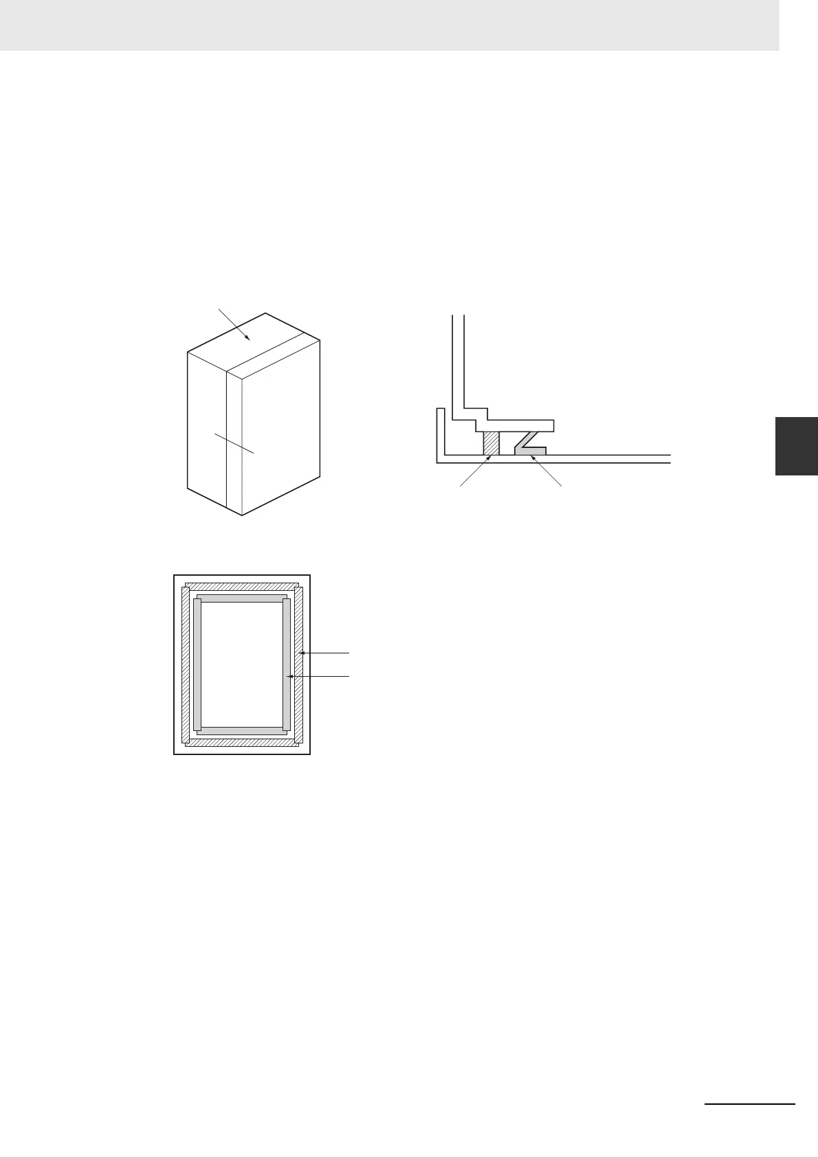
Door Structure
• Use a metal door.
• Use a water-draining structure where the door and case fit together, and leave no gaps. (Refer to
the diagrams.)
• Use a conductive gasket between the door and the case. (Refer to the diagrams.)
• Strip the paint off the sections of the door and case that will be in contact with the conductive
gasket (or mask them during painting), so that they are electrically conductive.
• The panel may warp and gaps may appear when screws are tightened. Be sure that no gaps
appear when tightening screws.
Case
Door
Control Panel
Door (Interior Side)
A
B
A-B Cross-section Diagram
Oil-resistant gasket
Conductive gasket
Door side
Oil-resistant
gasket
Conductive gasket

 Loading...


