3 - 33
3 Specifications
OMNUC G5-series (Pulse-train Input Type) AC Servomotors and Servo Drives User’s Manual
3-1 Servo Drive Specifications
3
3-1-10 Analog Monitor Connector Specifications (CN5)
Monitor Output (CN5)
Connectors for CN5 (6 Pins)
3-1-10 Analog Monitor Connector Specifications (CN5)
Monitor Output Signal Table
Pin
No.
Symbol Name Function and interface
1 AM1 Analog monitor
output 1
Outputs the analog signal for the monitor.
Default setting: Motor rotation speed 1 V/(500 r/min)
The item and the unit can be changed using Pn416 and Pn417.
The output method can be changed using Pn421.
2 AM2 Analog monitor
output 2
Outputs the analog signal for the monitor.
Default setting: Torque command 1 V/(33%)
The item and the unit can be changed using Pn418 and Pn419.
The output method can be changed using Pn421.
3 GND Analog monitor
ground
Ground for analog monitors 1, 2
4 – Not used Do not connect.
5 – Not used Do not connect.
6 – Not used Do not connect.
Name Model Manufacturer
Connector housing 51004-0600 Molex Japan
Connector terminal 50011-8000 Molex Japan
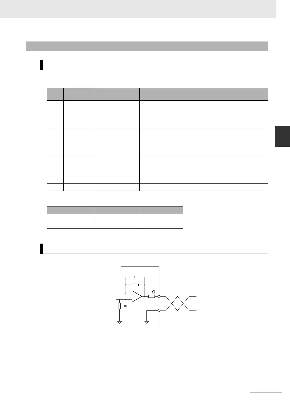
Monitor Output Circuit
Servo Drive
Monitor equipment
3
GND
1/2 AM1/AM2
1 k
+
–
 Loading...


