6 - 43
6 Applied Functions
OMNUC G5-series (Pulse-train Input Type) AC Servomotors and Servo Drives User’s Manual
6-12 Gain 3 Switching Function
6
6-12-1 Outline of the Function
6-12 Gain 3 Switching Function
You can newly set Gain 3 right before stopping to the gain switching function in Gain Switching
Input Operating Mode Selection (Pn114).
You can use the Gain 3 switching function for position control in the following situations.
• The servo is ON.
• The Servomotor can rotate normally without any failures.
Example: Switching Mode in Position Control = 7, Switching Condition = Position Command Input
Precautions for Correct UsePrecautions for Correct Use
• If Gain 3 is not used, set both Gain 3 Effective Time (Pn605) and the Gain 3 Ratio Setting
(Pn606) to 0.
• In the Gain 3 region, only the position loop gain and the speed loop gain are treated as Gain 3
and the Gain 1 setting is applied to other gains.
•
If the Gain 2 switching condition is established in the Gain 3 region, operation switches to Gain 2.
• If Gain 2 switches to Gain 3, the Position Gain Switching Time (Pn119) is enabled.
• There is a Gain 3 region even when Gain 2 is switched to Gain 1 due to a parameter change
and so forth.
6-12-1 Outline of the Function
6-12-2 Parameters Requiring Settings
Parameter No. Name Description Reference
Pn605 Gain 3 Effective Time Set the time during which Gain 3 is enabled. P.7-55
Pn606 Gain 3 Ratio Setting Set Gain 3 as a multiple of Gain 1. P.7-55
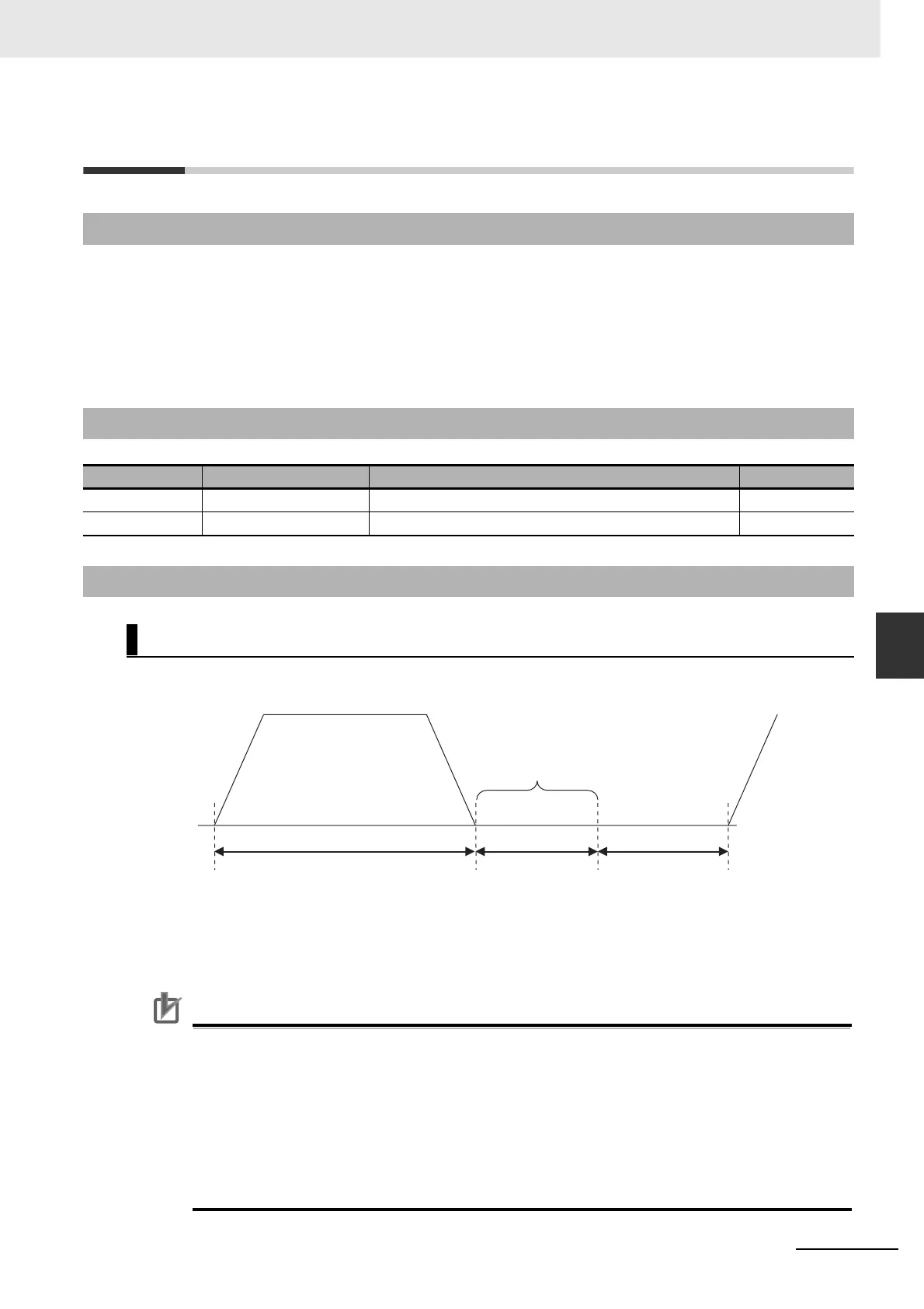
6-12-3 Operation
Operation Timings of Gains 1, 2 and 3
Gain 2
Gain 3
Gain 1
Position command speed [r/min]
Pn605 × 0.1ms
Pn105 to Pn109
Gain 3 region
Position loop gain = Pn100 × Pn606/100
Speed loop gain = Pn101 × Pn606/100
The Gain 1 values are used for the speed loop integral time constant, speed feedback
filter time constant, and force command filter time constant.
Pn100 to Pn104

 Loading...


