8 - 7
8 Operation
OMNUC G5-series (Pulse-train Input Type) AC Servomotors and Servo Drives User’s Manual
8-4 Mode Setting
8
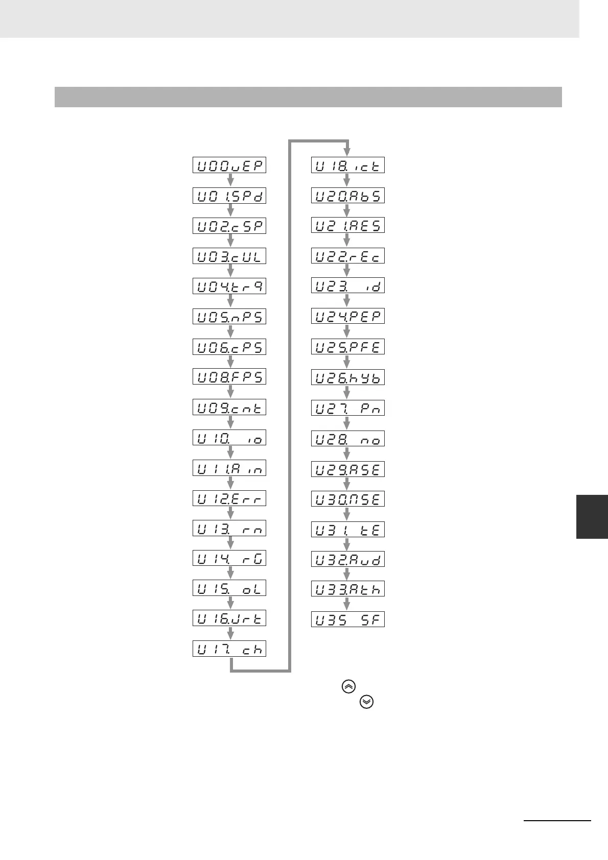
8-4-2 Monitor Mode
• The display shows the motor rotation speed when the power supply is turned ON for the first time
after purchase. To change the display that appears when the power supply is turned ON, change the
value set in Default Display (Pn528). For details, refer to Pn528 Default Display on page 7-53.
8-4-2 Monitor Mode
Press to move in the direction of the arrow.
And press to move in the opposite direction.
Position Command Error
Motor Rotation Speed
Position Command Speed
Speed Control Command
Torque Command
Total Encoder Pulses
Total Command Pulses
Reserved
Control Mode
I/O Signal Status
Reserved
Alarm Factor, History
Warning Number
Overload Load Ratio
Inertia Ratio
Reason for No Rotation
Reserved
Reserved
Reserved
Position Error (encoder units)
Reserved
Reserved
P-N Voltage
Software Version
Drive Serial Number
Motor Serial Number
Accumulative Operation Time
Automatic Motor Recognition
Function
Drive Temperature and Encoder
Temperature
Reserved
Regeneration Resistance
Load Ratio
Monitor for the Number of
Encoder Communications Errors
Display of the Number of
I/O Signal Changes

 Loading...


