6 - 33
6 Applied Functions
OMNUC G5-series (Pulse-train Input Type) AC Servomotors and Servo Drives User’s Manual
6-9 Sequence I/O Signals
6
6-9-1 Outline of the Function
6-9 Sequence I/O Signals
• You can set sequences in various operating conditions.
• For the connection of I/O signals and processing of external signals, refer to 3-1-4 Control I/O
Connector Specifications (CN1) on page 3-9.
You can allocate any functions to the input pins of the control I/O connector (CN1). In addition, you can
change the logic. However, some signals have limitations in the allocation. Refer to Input Signal
Allocation Method on page 6-34 for details.
If you replace a G-series Servo Drive, use the G5-series Servo Drive with the default settings.
The allocations of the default input signals are as follows. Refer to Input Signal Allocation Method on
page 6-34 when you change the allocation to use.
NO and NC in the Logic column above refer to the following states.
NO: Disabled (OFF) when signal input is open with COM-
Enabled (ON) when signal input is shorted with COM-
NC: Disabled (OFF) when signal input is shorted with COM-
Enabled (ON) when signal input is open with COM-
6-9-1 Outline of the Function
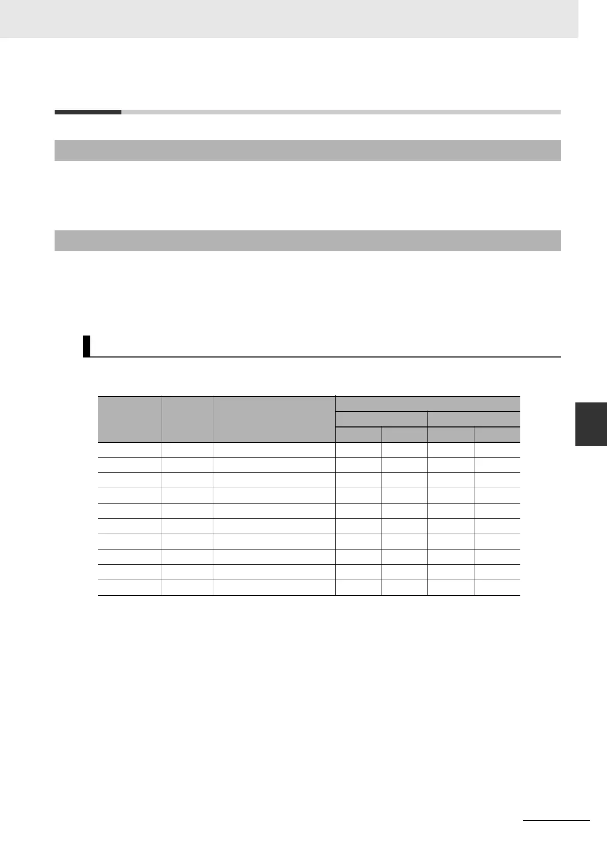
6-9-2 Input Signals
Default Input Signal Settings
Parameter
Input
signal
Default setting
Default setting state
Position control Speed control
Signal logic Signal logic
Pn400 SI1 00828282 hex (8553090) NOT NC NOT NC
Pn401 SI2 00818181 hex (8487297) POT NC POT NC
Pn402 SI3 0091910A hex (9539850) DFSEL1 NO VZERO NC
Pn403 SI4 00060606 hex (394758) GSEL NO GSEL NO
Pn404 SI5 0000100C hex (4108) GESEL1 NO VSEL3 NO
Pn405 SI6 00030303 hex (1979379) RUN NO RUN NO
Pn406 SI7 00000f07 hex (3847) ECRST NO VSEL2 NO
Pn407 SI8 00040404 hex (263172) RESET NO RESET NO
Pn408 SI9 00050505 hex (328965) TVSEL NO TVSEL NO
Pn409 SI10 00000E88 hex (3720) IPG NC VSEL1 NO
 Loading...


